
A protective coating can meet its specified dry film thickness and still contain a pinhole, void, missed edge, or other discontinuity that exposes steel. These small defects are commonly called holidays. In wet, buried, immersed, or chemically aggressive service, a holiday can become a direct path for corrosion even when the surrounding coating looks sound.
A defensible holiday-detection plan matches the instrument and test voltage to the complete coating system, confirms that the film is adequately cured, and defines what happens after an indication. The test is not a substitute for surface preparation, visual inspection, or dry film thickness measurement. It is a separate continuity check with its own risks and limitations.
What holiday detection can and cannot prove
ASTM D5162-24 covers electrical detection of discontinuities in nonconductive protective coatings on metallic substrates. The instrument completes an electrical path through a break in the coating to the conductive steel. The indication identifies a location that requires examination; it does not by itself identify the defect’s cause, dimensions, or remaining service life.
Holiday testing does not demonstrate adhesion, correct surface cleanliness, correct mixing, full cure, chemical resistance, or uniform thickness. Those controls remain part of the broader steel coating QA/QC plan. Verify thickness separately using an appropriate dry film thickness inspection.
Define the service need before specifying the test
The required degree of continuity depends on the coating system, steel geometry, and exposure. A lining in immersion or containment service may demand a much stricter continuity requirement than an atmospheric architectural topcoat. The owner, designer, coating manufacturer, and applicator should agree on the governing standard, test method, acceptance criteria, repair procedure, and retest scope before work begins.
Do not write a generic requirement to “holiday test all coatings” without checking applicability. ASTM D5162 addresses new nonconductive coatings on metallic substrates. Conductive pigments or fillers, zinc-rich layers, metallized surfaces, moist or contaminated films, and previously exposed linings can change the electrical response. The coating manufacturer should confirm whether the complete system can be tested and at what stage.
Coordinate the specification documents
Resolve conflicts among the project specification, product data sheet, manufacturer instructions, ASTM D5162-24, and AMPP SP0188-2024 before field testing. Record the document editions used. Avoid copying an old voltage rule into a new project: the current AMPP revision was developed in part because older high-voltage rules were not adequately tied to coating behavior and electrical principles.
Low-voltage wet-sponge testing
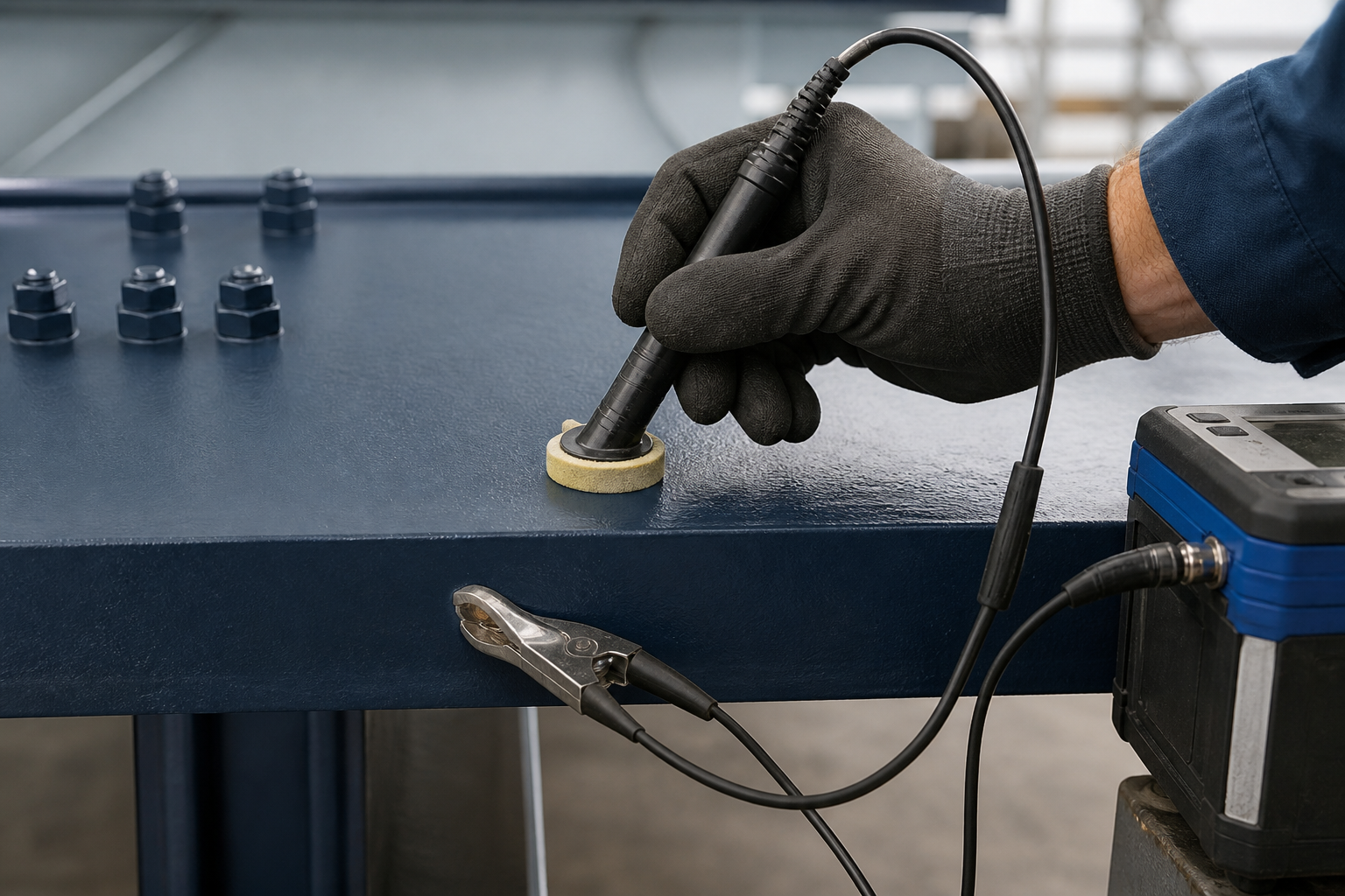
A low-voltage wet-sponge detector uses a damp conductive sponge connected to the instrument and grounded substrate. When the sponge passes over a discontinuity, the circuit closes and the instrument indicates the location. ASTM D5162 generally uses this approach for coatings or linings with total thickness of 0.5 mm (20 mil) or less.
The sponge must be wet enough to make contact without flooding the surface or creating long conductive trails. Corners, welds, edges, bolts, and complex details require deliberate scanning because contact can be incomplete. Move at the procedure’s controlled rate with overlapping passes, and maintain contact rather than hopping across texture.
Low-voltage testing is comparatively gentle, but it is not automatically valid for every system. Surface moisture, salts, dirt, conductive fillers, exposed metal at boundaries, and poor grounding can produce misleading indications. The inspector should prove instrument operation on a known discontinuity or suitable check feature before use and repeat the functional check at defined intervals.
High-voltage spark testing
A high-voltage detector establishes an electrical field between an electrode and the grounded steel. A discontinuity permits a discharge and triggers an indication. ASTM D5162 generally uses high-voltage equipment for coating or lining systems thicker than 0.5 mm (20 mil). It also allows limited use between 0.25 and 0.5 mm (10 and 20 mil) when voltage is correctly calculated and the coating manufacturer approves.
Excess voltage can puncture or weaken an otherwise sound film. Insufficient voltage may miss defects. Determine the setting from the governing current procedure, verified total film thickness, dielectric properties, manufacturer guidance, and relevant atmospheric conditions. Do not rely on an informal volts-per-mil shortcut.
High-voltage equipment also creates ignition and electrical hazards. Never test until the coating has dried and cured as required and retained solvent risk has been addressed. Evaluate confined spaces, flammable atmospheres, nearby sensitive equipment, access, grounding, and worker protection through the project safety process. Only trained personnel should operate the detector.
Build a field-ready test procedure
The written procedure should identify the coated areas and boundaries, coating system and nominal thickness, cure requirement, detector type, electrode configuration, voltage-setting basis, scan rate, coverage pattern, grounding method, function checks, weather limits, defect-marking method, repair material, retest timing, and acceptance authority.
Confirm cure and condition
Consult the manufacturer for the minimum cure before testing. An uncured film can retain conductive solvents, suffer damage, or present a fire risk. Confirm that the surface is clean and dry for the selected method, that environmental conditions are within the procedure, and that the substrate connection provides a reliable electrical return path.
Measure the actual coating build
Holiday-detector selection and voltage depend on the total coating build, not merely the nominal thickness of one coat. Review the DFT map, including local highs over welds and stripe-coated details. If thickness varies widely, the approved procedure should explain how settings or zones will be controlled without damaging thinner areas or missing defects in thicker ones.
Prove the complete circuit
Before production scanning, verify detector condition, battery or power status, leads, ground connection, electrode, audible or visual indicator, and the selected setting. Demonstrate response using a known holiday or manufacturer-approved verification device. Repeat after interruptions, setting changes, electrode changes, suspected malfunction, and at the end of the shift.
Scan systematically
Divide the structure into traceable areas. Use overlapping passes and a controlled speed. Give special attention to welds, edges, corners, cutouts, attachments, fasteners, transitions, and repaired zones. Mark each indication with a removable method that will not contaminate the coating. Never gouge the film merely to create a location mark.
Disposition, repair, and retest
Every indication should receive a unique location reference. Visually examine the area and confirm the indication according to the procedure. Record member, face, station or grid, detector, setting, coating thickness, date, inspector, and environmental conditions. A drawing or photo map is much more useful than a total defect count with no locations.
Prepare and repair confirmed defects using the approved coating manufacturer’s procedure. That may require feathering, cleaning, restoring specified coats, and observing recoat and cure windows. Repairing only the visible pinpoint without treating weak surrounding material can leave the defect unresolved.
Retest the repaired area after the repair coating has adequately cured. Include enough adjacent coating to verify continuity at the repair boundary. Repeated clusters should trigger a cause review: poor application technique, porous film, sharp edges, inadequate stripe coating, contamination, outgassing, or an unsuitable test setting may be producing a systemic problem.
QA/QC hold points for owners and inspectors
- Approve the coating system, exposure-based continuity requirement, standard, method, and acceptance criteria before application.
- Confirm substrate preparation and soluble-contaminant controls under the project’s coating inspection plan.
- Verify each coat, stripe coat, recoat interval, and total DFT before continuity testing.
- Obtain written manufacturer confirmation for cure time, detector compatibility, and voltage basis where required.
- Approve trained personnel, calibrated or verified equipment, grounding, electrode, scan speed, and coverage map.
- Witness initial function checks and representative production scanning, especially at complex details.
- Require traceable defect records, approved repairs, cure, and documented retesting.
- Close the hold point only after unresolved indications and repeated-defect causes are dispositioned.
The Bureau of Reclamation protective-coatings inspection guide places holiday testing within a much wider inspection program. That context matters: continuity testing is strongest when tied to surface preparation, environmental records, application inspection, DFT, cure, repairs, and closeout documentation.
Important limitations
Geometry can prevent full electrode contact. Conductive coatings can make the method inapplicable. Moisture or contamination can cause current to travel across the surface and produce false or displaced indications. Previously immersed linings may absorb moisture, causing misleading results or damage during high-voltage testing. Access restrictions can leave untested areas unless they are identified in advance.
A no-holiday result means no discontinuity was detected under the recorded conditions with the specified equipment and procedure. It does not guarantee future coating performance. Mechanical damage after the test, incomplete cure, poor adhesion, excessive stress, UV exposure, chemical attack, or movement can still create defects later. Owners should integrate coating inspection with the wider steel corrosion and section-loss assessment when deterioration is already present.
FHWA laboratory work on bridge coating systems documented that application defects and detected holidays could be associated with later rusting and blistering. The evidence supports finding and repairing discontinuities, but field performance still depends on the complete coating system and exposure, not one test result alone.
Frequently asked questions
Is holiday testing the same as dry film thickness testing?
No. DFT testing measures coating thickness at sampled locations. Holiday testing searches for electrically detectable breaks in a nonconductive film. A coating may pass one test and fail the other.
Should every steel coating be holiday tested?
No. The need depends on service exposure, coating type, conductivity, thickness, substrate, and project requirements. The designer and manufacturer should confirm applicability and acceptance criteria.
When is a wet-sponge detector used?
Under ASTM D5162-24 it is generally used for nonconductive coating systems 0.5 mm (20 mil) or less in total thickness. The approved project procedure and manufacturer instructions remain controlling.
Can high voltage damage the coating?
Yes. An excessive or inappropriate setting can puncture or weaken a film. Base the setting on the current standard, actual total thickness, dielectric behavior, atmospheric conditions, and manufacturer approval.
What happens after a holiday is found?
Mark and document the location, confirm and examine the defect, prepare and repair it using the approved coating procedure, allow the repair to cure, then retest the repair and its boundary.
Turn continuity testing into a controlled acceptance decision
Structural Rehab can help owners prepare steel coating specifications, inspection and test plans, hold points, defect maps, and repair acceptance criteria for bridges, buildings, tanks, and industrial structures. Book a structural rehabilitation consultation to review a coating failure or an upcoming corrosion-protection scope.
Sources and further reading
- ASTM D5162-24, Standard Practice for Discontinuity (Holiday) Testing of Nonconductive Protective Coating on Metallic Substrates
- AMPP SP0188-2024, Discontinuity (Holiday) Testing of New Protective Coatings on Conductive Substrates
- Bureau of Reclamation, Guide to Protective Coatings Inspection and Maintenance
- FHWA-HRT-11-046, Performance Evaluation of One-Coat Systems for New Steel Bridges
Need a professional structural assessment?
Book a consultation with Structural Rehab to evaluate repair priorities, corrosion risks, and rehabilitation options before damage escalates.
Book Consultation