
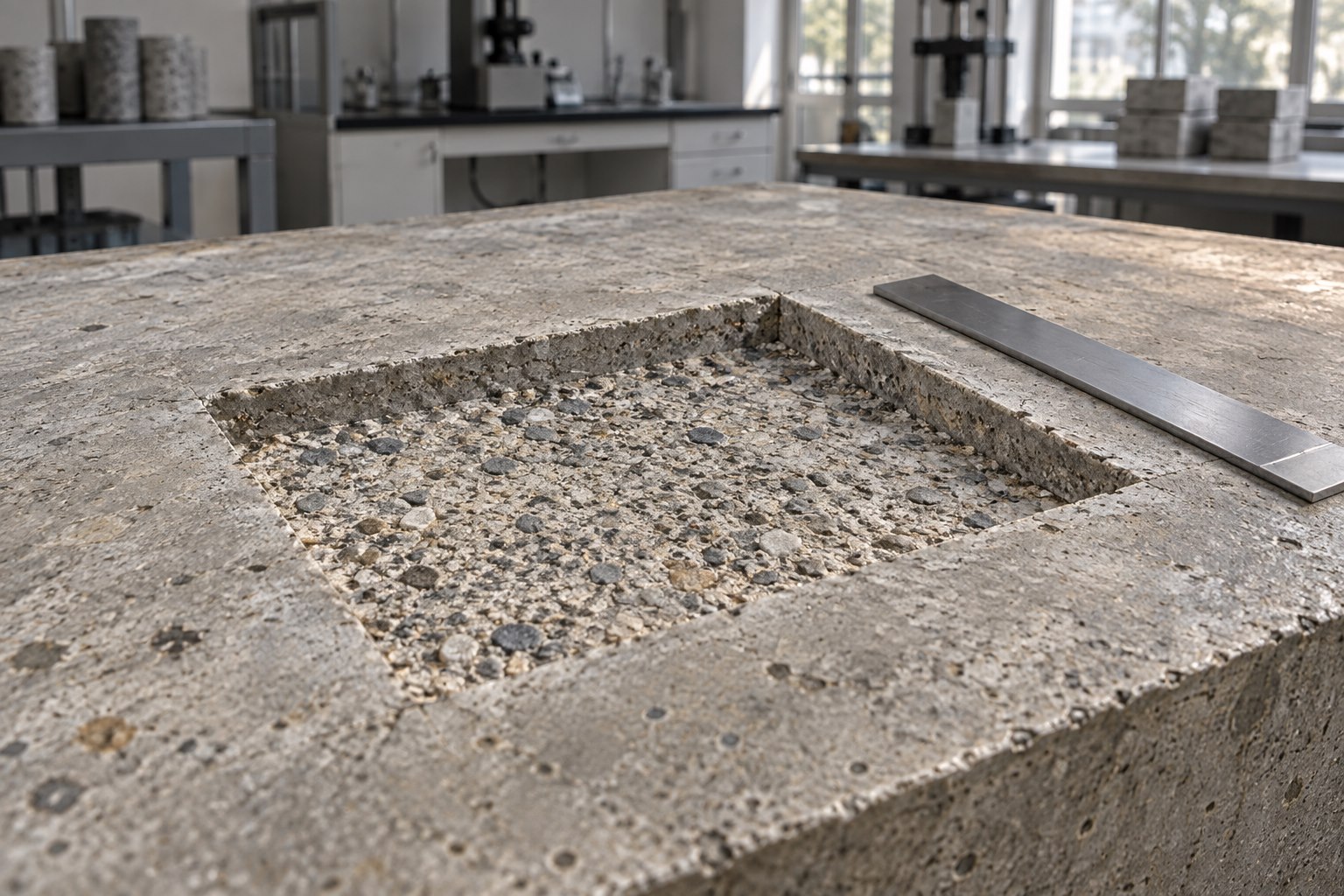
Concrete repair saw-cut boundaries define the edge of a patch, but drawing a rectangle around a spall is only the beginning. The proposed perimeter must suit the repair material, avoid embedded items, and remain open to revision when removal reveals more damage. A neat saw line does not certify the concrete behind it.
This guide focuses on the decision to approve a localized patch boundary in an existing concrete building or bridge. It offers a practical record and review workflow for engineers, inspectors, and owners. It is not a universal cutting detail: depth, geometry, removal sequence, and structural restrictions must come from the approved repair design and the selected system.
Define what the perimeter needs to achieve
The boundary should give the repair a buildable termination rather than a taper that the material cannot accommodate. It also needs to describe where removal may occur without leaving the crew to guess. These are separate questions. A line that looks tidy on a drawing can be unsuitable if reinforcement is close to the surface or deterioration continues beyond it.
For its intermediate-spall procedure, TxDOT specifies perimeter cutting to eliminate feathered edges and maintain at least a half-inch material depth, and prohibits corner overcuts. Those requirements belong to that procedure; do not adopt the dimension as a default for every repair product or structural member.
At the planning meeting, write down the document that controls the edge detail. If the specification, drawing, and material instructions disagree, assign the discrepancy to the responsible engineer before cutting. An inspector should not have to choose between conflicting documents while a saw is already operating.
Approve the cutting envelope before the line
Check embedded items and uncertainty
Identify reinforcement, prestressing, conduits, and other embedded items before authorizing intrusive work. Use available drawings together with a suitable field investigation; drawings alone may not describe the installed position. Our guide to locating reinforcement before concrete repair explains why instrument findings also need interpretation.
The release record should distinguish a measured location from an assumed one. For example, a marked bar line without a reliable cover estimate does not establish a permissible cutting depth. Ask the engineer to define what uncertainty is acceptable and where further investigation is needed. Keep unresolved areas visibly excluded from the cutting release.
Separate perimeter cutting from deeper removal
Record the permitted perimeter treatment and the permitted removal extent separately. Approval to trim an edge must not be read as permission to excavate the full enclosed area to any depth. The method statement should identify who can authorize an enlargement and how work stops when the exposed condition differs from the drawing.
Prestressed members require particular care. TxDOT’s procedure calls for engineer consultation when strands are exposed and warns against damaging them during removal. Unexpected strand exposure should therefore trigger review, not a routine change in tool position. The project engineer must also determine whether load restrictions or temporary support are needed before section removal begins.
Plan corners and awkward intersections
A circular blade does not automatically create a fully finished internal corner without extending its surface cut. The contractor should propose a corner-finishing method that meets the approved detail without driving cuts into retained concrete. Include this operation in the trial area or method review instead of treating it as an incidental finishing task.
Photograph each corner before it becomes hidden by repair mortar. If a cut runs beyond the intended perimeter, record its location and approximate extent and obtain a disposition. Do not silently fill the overcut and call the original boundary accepted. The engineer needs the opportunity to assess whether the additional cut changes the repair detail or requires separate treatment.
At joints, drains, penetrations, and existing patches, prepare a specific transition sketch. State whether the repair terminates at the feature, continues around it, or requires a separate detail. Avoid letting an inconvenient intersection become an undocumented thin strip. Where movement is intended, have the designer resolve the joint treatment rather than allowing patch material to bridge it by default.
Do not confuse roughness with undamaged concrete
ACI PRC-364.7-21’s public abstract describes bruising as a weakened surface layer containing interconnected cracks caused by high-impact removal or preparation. It notes that the condition can reduce repair bond strength and can be investigated with pull-off testing and petrographic examination. Visible texture alone is therefore insufficient evidence of a sound substrate.
For this boundary review, ask the contractor to show how retained edges will be protected during removal and how suspect areas will be investigated afterward. Identify the tool and technique used in the accepted trial area so that a later equipment change is visible in the inspection record. A change that affects the retained substrate should be reviewed before it becomes the production method.
Surface texture still matters, but it answers a different inspection question. Use the separate concrete surface profile guide to coordinate texture requirements with the repair system. Neither an attractive edge nor a rough cavity floor should close an unresolved soundness concern.
Revise the boundary when the evidence changes
The first marked outline is a proposed work limit, not proof that deterioration ends there. A useful project procedure gives the inspector a clear route to report continuing defects without informally enlarging the repair. This is especially important when neighboring patches begin to merge or removal approaches a support, anchorage, or member edge.
Consider a hypothetical beam-side patch: removal exposes a hollow-sounding area beyond one side of the approved outline. The crew records the finding and pauses the affected operation. The engineer reviews the newly exposed condition and issues a revised limit or requests more assessment. The inspector then records the new geometry and checks that it remains compatible with the material and structural restrictions.
This example is a documentation workflow, not a field diagnosis or an instruction to expand every patch. Some findings require a broader repair strategy. Keep a revision history so that the final record explains why the installed patch differs from the tender drawing. Owners can then distinguish justified additional work from an unexplained increase in quantities.
Use tests for the question they can answer
ASTM C1583/C1583M-25 covers direct-tension testing that can assess near-surface concrete tensile strength before repair, or the controlling failure strength of an installed repair system. Its public significance-and-use section emphasizes reporting the failure mode. The number alone does not establish whether failure occurred in the substrate, repair, or interface.
Where testing is specified, the engineer should define locations, acceptance criteria, and the response to unsuitable results before work is concealed. Keep results tied to the actual prepared area and its preparation date. A passing result elsewhere on the structure should not automatically release a visibly different edge condition. Testing also does not authorize cutting through an embedded item or establish the member’s remaining load capacity.
Create a short boundary-release record
The following is a suggested project record, to be adapted by the responsible engineer. It makes the cutting decision traceable without repeating the entire repair specification:
- Location: member identifier, face, patch reference, and photographs showing the surrounding structure.
- Controlling detail: drawing revision, repair system, approved edge geometry, and applicable limitations.
- Embedded-item review: investigation reference, unresolved areas, and the authorized cutting envelope.
- Method: perimeter and corner treatment, removal sequence, and any accepted trial-area reference.
- Findings: unexpected exposure, overcuts, continuing defects, and instructions issued in response.
- Disposition: accepted, accepted with defined restrictions, or held pending further review, with the responsible person’s name and date.
Keep cutting release distinct from placement release. After removal, the full cavity still needs the appropriate preparation and inspection. The ACI RAP-6 field guide places substrate preparation within a wider repair process that includes material selection, application, and curing. Boundary acceptance is one part of that process, not a substitute for the remaining checks.
Frequently asked questions
How deep should every concrete repair saw cut be?
There is no single depth suitable for all existing members and products. Use the approved detail, verified embedded-item constraints, and repair-system requirements. A dimension copied from another agency’s procedure needs a project-specific applicability check.
Can an overcut simply be covered with mortar?
It should first be documented and reviewed. Covering the cut would remove the opportunity to inspect it directly. The responsible engineer should decide its treatment and record any change to the repair detail.
Does a straight perimeter prove that removal is complete?
No. Geometry and substrate condition are separate acceptance questions. Continuing defects or an uncertain prepared surface require investigation even when all four edges look clean and regular.
Who should approve a larger patch?
Use the authority defined in the project inspection plan. Changes affecting structural removal, embedded items, or repair design need the responsible engineer’s review. A revised quantity alone is not a technical approval.
Plan the detail before mobilizing
This guidance supports planning and inspection; it cannot determine a safe cutting depth or structural removal limit remotely. Arrange qualified engineering review and task-specific safety controls before intrusive work. To discuss the repair scope and the evidence needed for that review, book a Structural Rehab consultation. Bring the member drawings, condition photographs, proposed material, and any investigation results so the discussion starts with the actual constraints.
Need a professional structural assessment?
Book a consultation with Structural Rehab to evaluate repair priorities, corrosion risks, and rehabilitation options before damage escalates.
Book Consultation