
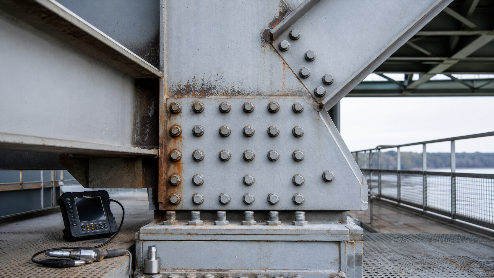
Bolted steel connection repair starts with a deceptively simple question: is the visible rust only a coating problem, or has the joint lost the geometry, clamping force, or steel area needed to transfer load? A few stained bolt heads do not answer that question. Neither does replacing isolated fasteners without understanding the load path.
Connections concentrate force and often trap water between plates, around bolt heads, and at member ends. The repair therefore has to address the connected plates, fasteners, faying surfaces, drainage, coating, and construction sequence as one system. This guide explains a practical owner-and-engineer workflow for assessing deteriorated structural steel bolted connections and controlling replacement work in buildings and bridges.
Why a bolted connection needs its own repair plan
A bolted joint transfers shear, tension, or a combination of actions through bearing, bolt shear, bolt tension, friction between prepared surfaces, or several mechanisms together. The required behavior depends on the original design and current demands. A repair that changes bolt type, hole condition, plate thickness, surface coating, or installation method can also change how the joint behaves.
Corrosion can reduce bolt diameter, enlarge holes, thin gusset or splice plates, and produce pack rust between plies. Expanding corrosion products may separate plates and bend local edges. Loose or missing fasteners can redistribute force to the remaining group. Fatigue cracking may initiate at holes, plate edges, or attachments and can be obscured by corrosion or coatings. These conditions are different from general member section loss, which is why connection-specific measurements and analysis matter.
For a broader approach to measuring deteriorated members, see our guide to structural steel section loss repair. At girder supports, also review the distinct stability and bearing issues discussed in steel girder end repair.
Start with records, load path, and access
Collect original drawings, previous repair details, inspection reports, load ratings, material information, and coating history before intrusive work. Confirm whether the joint is a field splice, gusset connection, beam-to-column connection, bracing connection, bearing connection, or secondary attachment. Identify which members deliver force to it and what would happen if one fastener or one connected ply stopped participating.
The engineer should establish whether the connection is bearing-type, pretensioned, or slip-critical, and whether fatigue, vibration, load reversal, seismic demand, or a nonredundant load path affects the evaluation. Existing bolts and rivets should not be assigned properties from appearance alone. Where documents are incomplete, material identification, representative testing, conservative assumptions, or a combination may be required.
Access planning is part of the assessment. Both sides of a joint may need inspection, and hidden interfaces may require selective disassembly. Before removing coatings, check applicable hazardous-material requirements. Before loosening any structural fastener, define temporary support, load restrictions, and the permitted sequence. Our article on temporary shoring and load-path control is concrete-focused, but its core lesson applies here: temporary works must be designed around the real force path, not treated as a site convenience.
Build an evidence-based condition map
Document what is visible
Assign a connection identifier and record member orientation, plate arrangement, bolt pattern, accessible sides, drainage path, coating condition, rust staining, deformation, missing hardware, and any sign of relative movement. Use scaled photographs and sketches. Compare current observations with earlier inspections when available. FHWA’s steel-superstructure corrosion protocol emphasizes consistent locations, measured extent, pitting depth, photographs, and comparison with prior data rather than an unrepeatable visual impression.
Measure plates, fasteners, and separation
After suitable surface preparation, use calibrated tools to measure remaining plate thickness and accessible fastener dimensions. Ultrasonic thickness testing can supplement direct measurements where geometry and surface condition permit. Map readings instead of reporting only the worst point. Measure gaps between plies, distorted plate edges, hole elongation visible at missing fasteners, and changes in alignment. Record the measurement method, calibration checks, nominal thickness, and uncertainty.
Pack rust deserves careful interpretation. A narrow rust line is not automatically a structural emergency, but forced separation can alter contact, introduce prying, retain moisture, and make new fastener installation unreliable. Do not simply draw plates together with new bolts unless the engineer has assessed the distortion, remaining thickness, fit-up, and effect on the joint.
Investigate cracks and movement
Clean suspect areas using a method suitable for inspection, then apply an appropriate nondestructive examination method selected by qualified personnel. Magnetic particle testing may be useful for surface and near-surface discontinuities in ferromagnetic steel; ultrasonic testing may suit other geometries. The inspection plan should define the area, surface condition, acceptance basis, and reporting. A crack at a hole or plate edge requires engineering evaluation; drilling its tip or welding over it without a designed procedure can leave the cause and remaining fatigue risk unresolved.
Evaluate the connection before choosing the repair
The structural assessment should use verified geometry and material properties to check all relevant limit states. Depending on the joint, these may include bolt shear and tension, combined actions, bearing at holes, tear-out, block shear, net-section rupture, gross-section yielding, plate buckling, prying, slip resistance, fatigue, and the capacity of connected members. The analysis also needs realistic load distribution when fasteners or portions of a plate are deteriorated.
The current RCSC Specification covers design, installation, and inspection of structural joints using high-strength bolts. It distinguishes snug-tightened, pretensioned, and slip-critical joints and defines approved installation and inspection approaches. It should be used with the governing structural design standard, project specification, and engineer’s assessment; it is not a field recipe for substituting any readily available bolt.
A key decision is whether the connection can remain safely loaded during work. Removing one bolt at a time sounds conservative, but it is not automatically safe. Load may already be concentrated in a few remaining fasteners, and removing corrosion products may expose thinner steel or release locked-in distortion. The repair sequence must state load limits, temporary support, maximum number and location of fasteners removed at once, and hold points for unexpected conditions.
Choose a repair that addresses the cause
Clean, seal, and recoat
If measured steel and fasteners remain acceptable and the joint has not separated or moved, the work may be primarily corrosion control. Detail preparation around bolt heads, plate edges, crevices, and difficult back sides. Correct leaking joints, blocked drainage, debris shelves, or coating discontinuities that caused persistent wetting. Coating acceptance should include surface preparation, environmental conditions, stripe coats where specified, dry-film thickness, holidays or discontinuities where relevant, and cure. See our steel coating QA/QC hold-point guide for those controls.
Replace fasteners
Fastener replacement requires a designed assembly and installation method. Specify bolt standard and grade, diameter, length, nuts, washers, coating or finish, joint type, installation method, and inspection. Confirm that replacement hardware is compatible as an assembly and with the exposure environment. Do not mix components casually or reuse high-strength bolts unless the governing requirements explicitly permit it.
RCSC recognizes installation methods such as turn-of-nut, calibrated wrench, twist-off-type tension-control bolt, and direct-tension-indicator methods, subject to its requirements. Published generic torque values are not a substitute for project-specific pre-installation verification and the selected approved method. AISC’s inspection guidance specifically warns that standard published torque values are not acceptable in place of actual calibrated values when torque is relevant.
Repair or reinforce plates
Where plates or holes are deficient, options may include engineered cover plates, splice plates, a revised bolt pattern, plate replacement, or a combination. New holes must avoid creating an inadequate net section, edge distance, spacing, or fatigue-sensitive detail. Existing holes may need measurement after controlled disassembly. Flame-cutting or enlarging holes without an approved procedure can damage edges and compromise fit.
Welded repairs to an existing bolted connection demand special care. The engineer must know or conservatively address base-metal weldability, restraint, fatigue category, access, coating removal, heat effects, and the interaction between welds and existing fasteners. A convenient weld is not necessarily a compatible load path. Use a qualified welding procedure and appropriate inspection whenever welding is part of the designed solution.
QA/QC hold points for bolted steel connection repair
- Before disturbance: approve the condition map, analysis assumptions, temporary works, load restrictions, and fastener-removal sequence.
- After cleaning: verify remaining thickness, pitting, cracks, plate separation, deformation, and hidden conditions against the repair drawings.
- Before installation: confirm fastener assembly documentation, storage, lot identification, hole condition, faying-surface condition, fit-up, and pre-installation verification.
- During installation: observe the specified sequence and method; document any bolt that cannot be installed or pretensioned as planned.
- Before coating: accept completed steelwork, edges, crevices, seal details, cleaning, and required NDE.
- At completion: record installed fasteners, inspection results, coating data, photographs, deviations, and as-built changes for future inspections.
The strongest repair record ties every accepted condition to a connection identifier and drawing location. A box marked “bolts checked” is not enough. The durable outcome is not merely a tight-looking bolt group; it is a verified force-transfer system with controlled water exposure and traceable installation evidence.
Limitations owners should understand
This article is general guidance, not a connection design or repair specification. Critical connections may require immediate access restriction, unloading, shoring, or emergency engineering review. Concealed corrosion, unknown materials, fatigue-sensitive details, fire or impact damage, and nonredundant members need project-specific investigation. Inspection results also represent conditions at a particular time; drainage and coating failures can restart deterioration if the exposure is not corrected.
For independent review of an assessment scope, repair concept, or QA/QC plan, book a Structural Rehab consultation. You can also explore our practical ebook on concrete and steel structures repair and protection through the site’s resources.
Frequently asked questions
Can one corroded structural bolt be replaced without shoring?
Not safely by assumption. The engineer should determine the connection’s current capacity, load distribution, redundancy, and removal sequence. Existing deterioration may mean the apparently isolated bolt is carrying more or less force than expected.
Does rust staining mean a bolted connection has failed?
No. Staining signals moisture and coating breakdown but does not quantify remaining capacity. Measure plate and fastener loss, check separation and deformation, investigate cracks, and assess the joint against its required actions.
Can new bolts pull pack-rusted plates back together?
That should not be attempted without engineering review. Pack rust can distort plates and conceal loss. Forced closure may damage components, change force distribution, or prevent reliable installation. The joint may need controlled disassembly, cleaning, measurement, plate repair, or replacement.
Is tightening by a generic torque value acceptable?
Generic published torque tables are not a substitute for the approved installation method, pre-installation verification, and project requirements. Fastener condition, lubrication, lot, and assembly behavior affect the relationship between torque and tension.
Authoritative references
- Research Council on Structural Connections, Specification for Structural Joints Using High-Strength Bolts
- AISC: RCSC Standard overview
- AISC engineering FAQs: high-strength bolting inspection
- FHWA bridge inspection resources and Bridge Inspector’s Reference Manual
- FHWA LTBP steel superstructure corrosion protocol
Need a professional structural assessment?
Book a consultation with Structural Rehab to evaluate repair priorities, corrosion risks, and rehabilitation options before damage escalates.
Book Consultation