
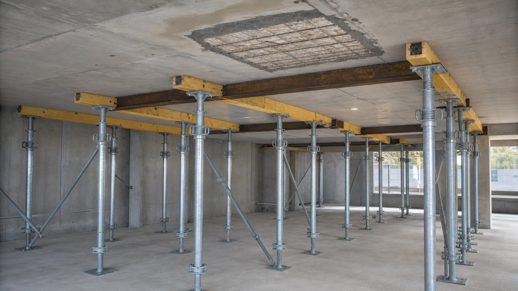
Concrete repair can temporarily make a structure weaker before it makes the structure stronger. Saw cutting, breakout, reinforcement exposure, load transfer, and staged placement can change the force path that existed before work began. Temporary shoring for concrete repair is therefore an engineered part of the repair—not a collection of adjustable posts selected after demolition starts.
Owners, designers, and contractors need a written plan that answers four questions: what must remain supported, where loads will go, how the temporary system will be installed and monitored, and what evidence will permit its removal. This guide explains those decisions without turning a general article into a project-specific shoring design.
Why concrete repair may need temporary shoring
Deteriorated concrete may still carry load, even when it cannot be credited at full design strength. Removing that material can reduce section depth, stiffness, shear capacity, confinement, bearing area, or continuity. Cutting reinforcement can create a much larger change. The risk is not limited to visibly severe damage: a modest repair opening at a critical column, beam end, slab strip, transfer element, or connection can alter load distribution.
Shoring may also be required to limit movement rather than prevent immediate collapse. Excessive deflection while a repair material is young can crack the new repair, damage its bond, jam bearings, distort partitions, or transfer unintended load into adjacent members. The key principle is simple: evaluate the temporary condition at every stage, not only the final repaired condition.
A sound repair investigation begins with mapped distress and a defined removal boundary. Our guide to concrete delamination surveys explains how sounding and nondestructive evaluation can reveal hidden extent before demolition. Field limits still need confirmation as concrete is opened.
Start with a temporary-condition load path
A temporary works plan should trace load from the member being repaired through headers, shores, braces, floors, foundations, or ground. Every interface matters. A strong shore standing on a weak slab, hollow masonry, unsuitable fill, or a poorly distributed base can simply move the failure point.
Define loads and changing stages
The design basis should identify dead load, occupancy and construction live load, stored materials, equipment reactions, impact, wind where relevant, and any project-specific lateral actions. It should also describe the sequence: installation, initial contact, controlled preload if specified, concrete removal, reinforcement work, placement, curing, load transfer, and dismantling. The governing stage may occur halfway through the work.
Do not assume that turning a screw jack until it feels tight creates a known force. Preloading can redistribute load, lift finishes, crack adjacent concrete, or overload the supporting level. If preload is required, the designer should define the method, target or movement criterion, measurement approach, and stop limits.
Check the receiving structure
When shores pass through several floors, their reactions may need to be carried down through reshoring or engineered distribution. Alignment, slab punching, beam capacity, foundation bearing, and differential settlement all deserve review. Where shores bear on soil, the support system must address ground capacity, drainage, softening, and suitable sills or footings.
FHWA guidance for temporary bridge supports emphasizes load distribution, foundation capacity, elevation tolerances, and settlement monitoring. The same reasoning is useful in building repair: the temporary support is only as reliable as its complete load path.
Roles and documents must be clear
ACI’s repair framework places explicit attention on stability, temporary shoring, construction stages, and quality assurance. The repair design professional should establish project criteria and identify where temporary support is required. A qualified temporary-works or specialty engineer commonly develops the detailed shoring design. The repair design professional reviews the proposed system for compatibility with the permanent structure and repair intent, while the contractor remains responsible for execution within the contract and approved procedures.
Those boundaries should be stated rather than assumed. A useful submittal normally includes design criteria and calculations, shore and brace layout, member capacities, base and head details, foundation or floor checks, installation sequence, preload instructions where applicable, inspection points, permitted construction loads, monitoring limits, contingency actions, and removal criteria. Revised field conditions require a controlled revision—not a verbal workaround.
OSHA’s cast-in-place concrete requirements provide a practical safety baseline: formwork and shoring must support reasonably anticipated vertical and lateral loads; drawings and revisions must be available at the jobsite; shoring equipment must be inspected; damaged equipment must not be used; sills must be sound and capable; and base plates, heads, extensions, and adjustment screws must have firm contact. Applicable local law and project specifications may impose additional requirements.
Build the demolition sequence around stability
Concrete removal should not outrun engineering knowledge. Before breakout, confirm the actual member geometry, reinforcement location, utilities, repair perimeter, and support arrangement. The rebar locating guide explains why cover meters, ground-penetrating radar, drawings, and selective verification should be combined before cutting or coring.
Sequence the work in bounded areas when simultaneous removals would create an unsafe or overly flexible condition. Typical controls may limit opening length, prohibit adjacent bays from being opened together, preserve selected reinforcement until load transfer is complete, or require one repair stage to reach a stated acceptance condition before the next stage starts. These are engineering decisions, not universal dimensions.
A pre-demolition hold point should confirm that shores and bracing match the approved layout; heads and bases are seated; connections are complete; exclusion zones and permitted loads are posted; monitoring readings are initialized; and the team understands stop-work triggers. Photograph and record the accepted condition.
Inspect and monitor during the work
Temporary works are exposed to changing loads, vibration, impact, water, temperature, and human activity. Inspection cannot end when the last shore is installed. A competent inspection plan should cover the period before demolition, during critical removal stages, after unexpected findings, during placement, and before load transfer or removal.
What field inspections should record
- shore identity, location, spacing, orientation, and extension;
- condition of posts, frames, pins, screws, braces, welds, and connections;
- full contact at heads, bases, wedges, distribution members, and sills;
- plumbness, alignment, eccentricity, accidental displacement, and missing bracing;
- support-floor or ground distress, crushing, punching signs, or settlement;
- construction loads, stored materials, equipment, and access changes;
- movement readings and comparison with alert and stop limits; and
- authorization and closeout of corrective actions.
Monitoring should match the consequence and expected behavior. Options include survey points, displacement gauges, telltales, load cells, strain instruments, or simple repeatable level checks. Instruments do not create safety by themselves. The plan needs baseline readings, frequency, responsible persons, alert limits, stop-work limits, communication routes, and predetermined actions. Read more about turning measurements into decisions in our structural monitoring guide.
Plan for changed conditions
Repair work routinely exposes conditions that drawings could not show: deeper delamination, severed bars, corrosion loss, voids, prior repairs, unexpected tendons, cracked support zones, or wet and unstable substrates. The safe response is to stop the affected operation, stabilize the area if necessary under an approved contingency, document the finding, and obtain engineering direction.
Crews should not widen a repair because loose concrete “keeps going” without checking the temporary-condition assumptions. Likewise, a shore should not be moved to improve access unless the approved sequence permits it. A field change that looks small can remove a designed support point or introduce eccentric load.
Coordinate repair placement and curing
Shoring must remain compatible with formwork, material delivery, consolidation, inspection, and curing. For deep vertical or overhead repairs, review the form-and-pour concrete repair guide. Before material goes in, use a formal pre-placement inspection hold point to verify substrate, reinforcement, geometry, moisture condition, materials, weather controls, and access.
Placement does not automatically restore capacity. The repair must develop the properties required by the design, and the interface and reinforcement details must perform as intended. Protect the repair from moisture loss, temperature extremes, vibration, impact, and premature loading. Our article on concrete repair curing and protection explains why early-age control belongs in the acceptance plan.
Do not remove shores by calendar alone
A preset number of days is not sufficient unless the design and specification deliberately use time together with defined materials and verified conditions. Removal criteria may include compressive strength or another relevant material property, completed curing, accepted bond or placement records, confirmation of member geometry, completion of adjacent stages, review of monitoring trends, and authorization by the responsible design professional.
OSHA states that forms and shores, apart from listed exceptions, are not to be removed until the concrete can support its weight and superimposed loads, based on the plans and specifications or appropriate strength testing. For repair work, the designer must translate that principle to the actual repair material, load path, and staged construction condition.
Load transfer should be gradual and sequenced when sudden release could shock the repaired member or overload neighboring supports. Record the order of release, observations, and movement readings. If behavior differs from the prediction, stop and review before continuing.
Owner’s temporary shoring checklist
- Require an evaluation of the existing and temporary structural conditions before demolition.
- Identify the qualified designer responsible for detailed temporary works.
- Demand a complete load path, staged sequence, calculations, drawings, and revision control.
- Confirm support floors, foundations, soil, sills, heads, and connections—not only shore capacity.
- Set pre-demolition, changed-condition, pre-placement, and removal hold points.
- Define permitted occupancy, storage, equipment, and construction loads.
- Establish monitoring methods, baselines, limits, reporting, and contingency actions.
- Require material and inspection evidence before load transfer.
- Keep the approved drawings and field records with the repair closeout file.
Limitations
This article is general guidance, not a shoring design, demolition procedure, or safety plan. Temporary works depend on the real structure, deterioration, load history, geometry, foundations, access, construction method, jurisdiction, and consequences of failure. A licensed or otherwise legally qualified design professional should evaluate the project. Contractors must also comply with applicable occupational-safety rules, manufacturer instructions, and site-specific requirements.
Frequently asked questions
Does every concrete repair need shoring?
No. The need depends on what capacity or stiffness is removed, existing demand and condition, member redundancy, demolition sequence, and construction loads. The decision should follow an engineering assessment rather than repair size alone.
Can adjustable steel props be installed without a design?
Adjustable props have rated capacities, but selecting posts is only one part of the system. Layout, bracing, eccentricity, extension, end restraint, load distribution, supporting-floor capacity, foundations, sequence, and monitoring must also be addressed.
Who should design temporary shoring for structural repair?
Project roles vary by jurisdiction and contract. A qualified specialty or temporary-works engineer commonly prepares the detailed design, while the repair design professional establishes criteria and reviews compatibility with the permanent structure and repair intent.
When can shoring be removed after repair?
Only after the project’s engineered removal criteria are met. These may include verified material strength, completed curing, accepted inspections, stable monitoring results, completion of dependent stages, and written authorization.
Authoritative sources
- American Concrete Institute: ACI 562 Repair Code portal
- ACI Concrete Q&A: Design professional responsibilities regarding shoring
- ACI resources on shoring, repair, and inspection
- OSHA 29 CFR 1926.703: formwork, shoring, reshoring, and removal
- FHWA guidance on temporary shoring supports and settlement control
Need an independent repair and temporary-works review?
Structural Rehab can help owners review investigation findings, repair sequencing, temporary-support criteria, QA/QC records, and load-transfer evidence. Book a structural rehabilitation consultation before demolition begins or when field conditions no longer match the repair documents.
Need a professional structural assessment?
Book a consultation with Structural Rehab to evaluate repair priorities, corrosion risks, and rehabilitation options before damage escalates.
Book Consultation