
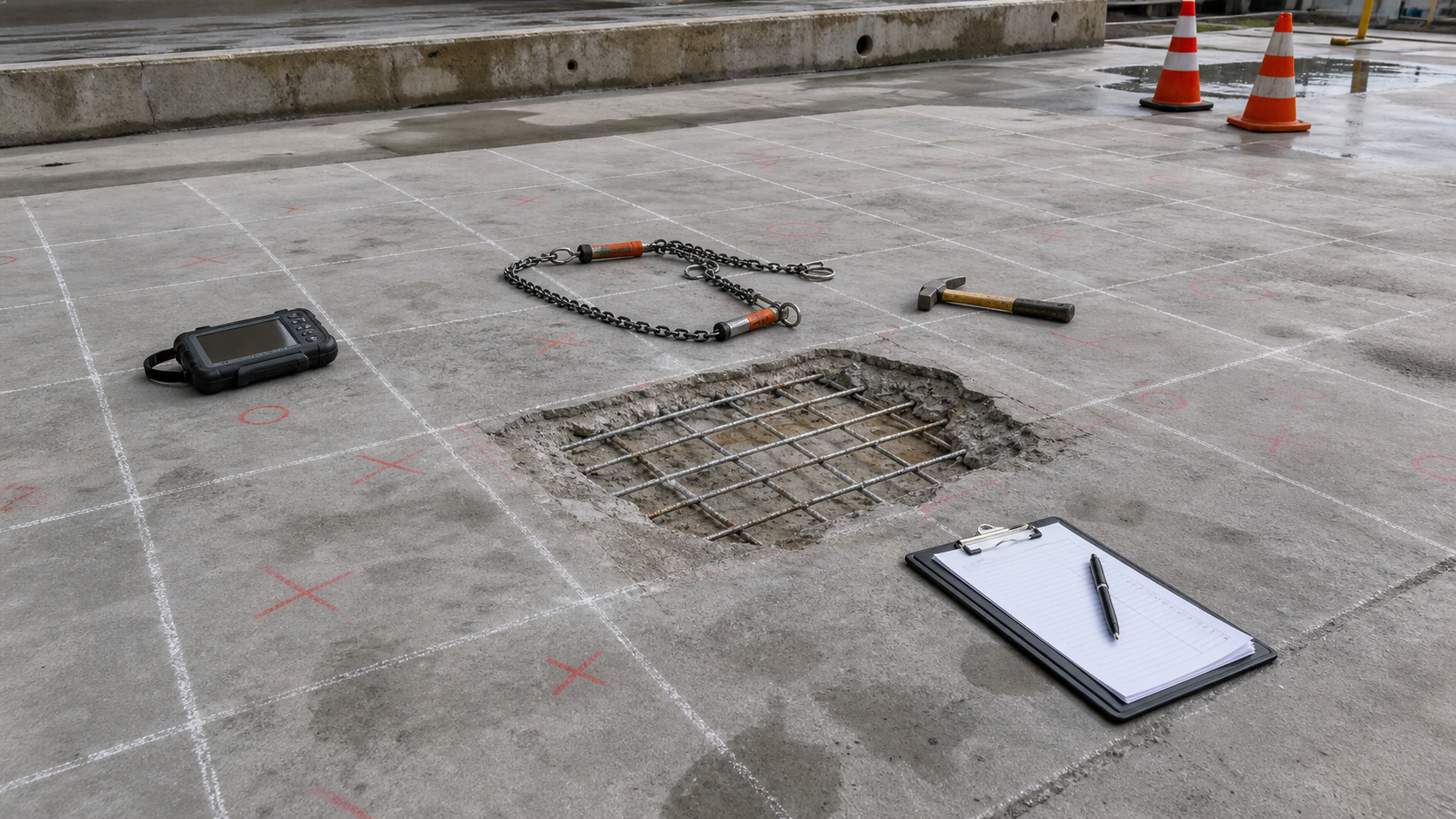
Concrete can look sound while a shallow plane below the surface has already separated. That hidden separation matters because patches, overlays, traffic coatings, FRP, and waterproofing systems all depend on a stable substrate. A concrete delamination survey is the step that turns uncertain repair limits into an engineering map. Done well, it helps owners price the work, decide whether a patch is enough, and avoid bonding a new system to concrete that is already detached.
The key point is simple: the delamination map is a repair boundary tool, not a decoration. It should be built from observations that can be repeated, checked, and tied to the likely cause of distress. That usually means visual review, hammer sounding or chain drag, selected nondestructive evaluation, corrosion testing where reinforcement is involved, and enough exploratory openings to confirm what the signals mean.
What Delamination Means in Structural Repair
Delamination is separation within the concrete section or at an interface. In reinforced concrete it is often related to corrosion products expanding around embedded steel, freeze-thaw damage, poor consolidation, previous overlay failure, alkali-silica reaction symptoms, fire damage, or fatigue and impact. The visible symptom may be a crack, rust stain, hollow sound, lifted overlay, or spall. Sometimes the only practical clue is a change in sound when the surface is struck.
That is why repair teams should avoid drawing limits from the visible spall alone. The loose edge of a spall is only the failure that has reached daylight. The surrounding concrete may have a larger debonded zone that will fail when demolition starts. If that zone is not mapped before tendering, the project can suffer quantity growth, change orders, and disputes about whether the deterioration was foreseeable.
Start With a Survey Grid and a Defect Language
A useful field survey starts with a grid that fits the structure. On bridge decks and slabs, the grid may follow lanes, bays, or stationing. On walls, soffits, beams, and columns, it may follow member lines and elevations. The grid does not need to be elaborate, but it needs to be traceable. Photographs, sketches, and markups should use the same references so a designer can compare delamination, cracking, leakage, corrosion potential, cover, and repair quantities without guessing where each note belongs.
The team should also define terms before the survey begins. Hollow sound, drummy sound, active spall, incipient spall, overlay debond, surface scaling, and crack map should not be mixed together. Each defect means a different repair risk. A hollow sound under an old overlay may lead to overlay removal. A hollow sound over reinforcing steel may need corrosion investigation and concrete removal behind the bar. A crack with no hollow response may require routing and sealing, injection, monitoring, or no repair depending on movement and exposure.
Hammer Sounding and Chain Drag
Hammer sounding and chain drag remain practical because they are fast, inexpensive, and directly connected to the repair crew’s experience. ASTM D4580/D4580M describes measuring delaminations in concrete bridge decks by sounding, and the concept is widely adapted for slabs and accessible concrete surfaces. A hammer gives better control in tight locations, vertical faces, soffits, edges, and around penetrations. Chain drag is efficient on horizontal decks and slabs where the operator can hear changes in tone while moving across the grid.
These methods are not magic. They depend on access, surface condition, background noise, operator consistency, concrete thickness, overlay type, moisture, and defect depth. A wet or rough surface can mask changes. Thick asphalt, membranes, tiles, or coatings can make results unreliable. For noisy sites, large areas, or disputed quantities, the survey should include a second method or verification openings. Sounding is strongest when it is treated as one layer of evidence, not the only proof.
Where NDE Adds Value
Nondestructive evaluation can improve confidence when defects are widespread, inaccessible, safety critical, or hidden below overlays. Impact echo, ultrasonic pulse methods, ground penetrating radar, infrared thermography, and robotic or automated sounding can each help in the right conditions. FHWA research on bridge deck NDE highlights that different technologies see different deterioration mechanisms, so method selection should follow the question being asked. Are we mapping delamination, cover, moisture, corrosion risk, section loss, voids, or overlay debond?
Infrared thermography can be efficient for large sun-exposed decks, but timing and environmental conditions control usefulness. Impact echo may identify internal reflectors and voids, but data interpretation requires skill. Ground penetrating radar is useful for reinforcement location, cover, and some deterioration indicators, but it is not a universal delamination detector. The practical approach is to use NDE to refine the map, prioritize openings, and reduce uncertainty, then confirm the repair assumption where the consequences of being wrong are high.
Connect Delamination to Corrosion and Moisture
A delamination map tells you where separation exists. It does not automatically tell you why. Before specifying repair, compare the map with corrosion indicators such as rust staining, cracking along reinforcement, cover depth, chloride profile, half-cell potential, concrete resistivity, and leakage history. Structural Rehab has separate guides on half-cell potential testing, concrete resistivity testing, and spalling repair diagnosis because those tests answer different questions.
If corrosion is active, removing only the hollow concrete may not be enough. The repair may need chloride-contaminated concrete removal, reinforcement cleaning or replacement, galvanic anodes, cathodic protection, waterproofing, drainage correction, or a different exposure strategy. If the delamination is mainly an overlay bond problem, the repair may focus on removal, surface profile, moisture condition, and bond testing. The repair design should follow the failure mechanism.
How to Turn the Survey Into Repair Limits
Repair limits should include the mapped delamination, a practical margin beyond the hollow response, and constructible edges that can be sawcut, chipped, cleaned, inspected, and reinstated. The margin is not a fixed number for every structure. It depends on reinforcement layout, expected deterioration beyond the sound change, edge geometry, traffic exposure, and whether the repair material can bond to the prepared concrete. ACI 562 is useful because it frames repair as assessment, design, execution, and quality assurance rather than isolated patching.
For bidding, separate confirmed delamination quantities from contingency quantities. Mark areas that need opening for verification. Include assumptions about access, demolition depth, reinforcement exposure, and disposal. For owners, this makes the estimate more honest. For contractors, it reduces the risk that every additional square meter becomes an argument. For engineers, it preserves a record of why the repair boundary was chosen.
Quality Checks During Demolition
The survey should not end when the contractor mobilizes. After removal begins, the exposed concrete should be sounded again. Edges that remain hollow should be extended. Reinforcement should be inspected for section loss, bar continuity, congestion, bond, and corrosion condition. If the original survey underestimated damage because an overlay masked the response, the engineer should update the repair map and decide whether the repair strategy still fits.
Before reinstatement, the prepared substrate should meet the specified cleanliness, profile, moisture condition, and soundness. Pull-off testing may be appropriate for bonded overlays or repair systems. Photographs of prepared areas, bar condition, repair depth, and final boundaries are not paperwork clutter; they are evidence that the repair was built on sound concrete.
Limitations Owners Should Understand
No delamination survey can remove all uncertainty. Some defects are too deep, too small, too wet, or too masked by surface systems to detect reliably with one method. Access restrictions may leave blind spots. Sounding results can vary between operators. NDE can produce false positives and false negatives when conditions fall outside the method’s assumptions. This is why the best deliverable is not just a colored map. It is a map with method notes, confidence levels, verification openings, photographs, and repair recommendations tied to observed causes.
FAQ
Is chain drag enough for a concrete delamination survey?
It can be enough for accessible horizontal surfaces when conditions are suitable and the project risk is modest. For critical members, overlay-covered areas, noisy sites, or disputed quantities, combine it with hammer sounding, selected NDE, and verification openings.
Should delaminated concrete always be removed?
Not automatically. The decision depends on location, depth, structural role, exposure, corrosion activity, future loading, and the intended repair system. Detached concrete in a load path, traffic surface, or overhead area usually needs more urgent action.
Can delamination be repaired without fixing corrosion?
Only when corrosion is not the driving mechanism or has been controlled. If chloride contamination, moisture, and active steel corrosion remain, a patch may fail around the edges even if the initial bond looks good.
Sources
- ASTM D4580/D4580M, sounding of concrete bridge deck delaminations
- FHWA, nondestructive evaluation guidance for bridge structures
- ACI CODE-562, Assessment, Repair, and Rehabilitation of Existing Concrete Structures
- ICRI technical guidelines for concrete repair practice
Need a repair scope that separates surface symptoms from hidden delamination? Book a Structural Rehab consultation or review our concrete and steel structures repair ebook for owner-focused decision guidance.
Need a professional structural assessment?
Book a consultation with Structural Rehab to evaluate repair priorities, corrosion risks, and rehabilitation options before damage escalates.
Book Consultation