
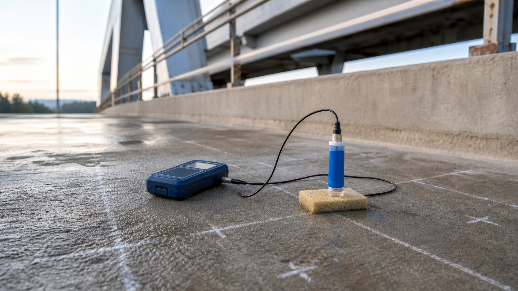
Corrosion can be active inside reinforced concrete before rust staining, cracking, or spalling becomes obvious. A half-cell potential survey helps an investigation team map where electrochemical conditions indicate a greater or lower likelihood of active reinforcement corrosion. It is a valuable screening tool, but it does not measure corrosion rate, steel section loss, or structural capacity.
This guide explains half-cell potential testing for reinforced concrete for owners, engineers, and inspectors. It focuses on planning, field control, interpretation, limitations, and the complementary evidence needed before repair boundaries or protection strategies are selected.
What half-cell potential testing measures
ASTM C876-22b covers corrosion-potential measurements of uncoated reinforcing steel in concrete. The test measures the voltage difference between electrically connected reinforcement and a stable reference electrode placed on the concrete surface. Readings collected on a planned grid can be contoured to show spatial patterns and potential gradients.
The reading is an electrical potential, not a direct loss-of-metal measurement. A map can identify areas that deserve closer investigation, establish a baseline, or help compare conditions over time. It cannot state how much bar has been lost, how fast corrosion is progressing, whether bond remains adequate, or whether a member is safe to carry load.
That distinction prevents a common error: treating the most negative reading as the location requiring the deepest repair. Repair decisions require physical condition data, exposure information, and structural judgment in addition to potential values.
Confirm the method is applicable
Identify the reinforcement and surface system
ASTM C876 applies to uncoated reinforcing steel. It is not applicable to epoxy-coated reinforcement. Waterproofing membranes between the steel cage and test surface can interrupt the electrical path, while coatings, sealers, overlays, and very dry concrete can make surface contact unreliable or impossible. Document these conditions before establishing a grid.
Metallic repair components, galvanized steel, embedded anodes, impressed-current cathodic protection, electrical grounding, and dissimilar reinforcement can also affect results. The responsible corrosion specialist should define how these features will be isolated, recognized, or addressed. Do not compare unlike electrode systems without applying the correct reference conversion.
Verify reinforcement continuity
The survey requires a direct electrical connection to the reinforcement and reasonable continuity across the area being mapped. FHWA guidance calls for checking continuity rather than assuming all bars are connected. Discontinuous bars, isolated mats, couplers, repairs, or construction joints may require multiple verified connections and separately interpreted survey zones.
Locate reinforcement before drilling or exposing a connection. The existing rebar locating guide explains why cover-meter or GPR work should precede intrusive access. The connection detail and restoration method should be approved by the owner and engineer.
Plan a survey that can be repeated
A defensible plan defines the purpose, accessible test area, grid spacing, electrode type, coordinate origin, connection points, surface-conditioning procedure, weather limits, and complementary testing. Grid spacing should reflect the size of the element and the decisions the map must support. A coarse reconnaissance grid may identify broad zones; tighter spacing may be needed near sharp gradients, repairs, joints, drains, or exposure changes.
Before fieldwork, record:
- structure, element, elevation, orientation, and drawing reference;
- reinforcement type, cover, mat, continuity zones, and connection method;
- surface treatments, overlays, patches, membranes, and visible moisture;
- reference electrode type, condition, identification, and verification;
- grid coordinates, spacing, omitted points, and reasons for omissions;
- ambient and concrete-surface temperature and relevant weather history;
- pre-wetting method, contact medium, stabilization rule, and repeat checks;
- planned chloride, carbonation, resistivity, delamination, and corrosion-rate data.
Photograph the grid and fixed reference points. A map without a traceable coordinate system is difficult to align with later sounding, sampling, repair, or monitoring work.
Control surface condition and equipment
Use a verified reference electrode
Copper-copper sulfate and silver-silver chloride reference electrodes are commonly used, but their voltage scales are different. Record the electrode chemistry with every dataset. Check the electrode against a stable reference according to the procedure and manufacturer guidance, inspect the porous tip, maintain the filling solution, and prevent contamination. A drifting electrode can shift an entire map.
Establish consistent electrical contact
FHWA’s LTBP protocol uses a wetted sponge and consistent probe pressure, avoids exposed aggregate or obstructions, and requires readings to stabilize before recording. Follow the governing project procedure. Concrete moisture strongly influences circuit resistance, so uncontrolled differences between dry and saturated areas can obscure the corrosion pattern.
Pre-wetting must be consistent and documented, without creating unsafe runoff or concealing surface features. Very dry interior or desert-exposed concrete may remain too resistive for the basic method. Surface-applied coatings or sealers can also prevent a valid circuit. Do not force a result from unstable equipment; mark the point invalid and investigate the cause.
Field workflow and QA/QC hold points
- Map the element. Establish coordinates and record patches, cracks, spalls, joints, drains, wet zones, and inaccessible areas.
- Locate steel safely. Confirm cover and bar position before making an approved connection.
- Check continuity. Demonstrate which reinforcement belongs to each electrically continuous survey zone.
- Verify the electrode and meter. Record instrument IDs, checks, polarity, cable condition, and reference type.
- Condition the surface. Apply the approved contact and pre-wetting procedure consistently.
- Collect stable readings. Use consistent placement and pressure, repeat questionable points, and record invalid or omitted locations.
- Review data in the field. Look for improbable jumps, uniform offsets, cable faults, lost continuity, or electrode drift before access is removed.
- Restore connection points. Patch approved access holes and document the restoration.
A useful hold point occurs after an initial map but before destructive sampling. The engineer can use gradients and condition evidence to choose representative high, intermediate, and low-potential locations rather than sampling only visibly damaged concrete.
Interpret maps without turning thresholds into verdicts
Potential criteria depend on the reference electrode and conditions. FHWA summarizes traditional ASTM C876 copper-copper sulfate guidance in which values more negative than -350 mV have been associated with a high probability of active corrosion, values less negative than -200 mV with a high probability of no active corrosion, and the range between them with uncertainty. These are probability-based interpretation bands, not universal pass/fail limits.
ASTM emphasizes specialist interpretation and complementary data. Cover greater than about 75 mm can average the response of adjacent reinforcement and reduce spatial discrimination. Temperature and humidity affect readings. Oxygen-starved areas can produce unusually negative values, and dense, wet, polymer-modified, coated, or electrically altered systems may behave differently from the conditions behind simple threshold rules.
Review the shape of the map, repeatability, local gradients, reinforcement layout, repairs, exposure, and instrument reference—not just one extreme number. Compare future surveys only when electrode type, coordinate system, surface condition, temperature, contact method, and reinforcement connection are sufficiently consistent.
Combine potential data with other evidence
Half-cell data becomes more useful when it is aligned with tests that answer different questions. Pair it with concrete resistivity testing to assess how readily ionic current can flow, and with linear polarization resistance testing when an estimate of corrosion rate is required and the method is suitable.
Use chloride profiling and carbonation depth testing to investigate likely causes. Align the map with visual survey, sounding, cover measurements, delamination mapping, exposure history, and selective openings that confirm steel condition and section loss.
Repair boundaries should not be drawn from half-cell contours alone. A very negative zone may have active corrosion without delamination, while an old delamination may remain after corrosion conditions change. Conversely, concrete near a patch may develop an unfavorable electrochemical relationship that deserves monitoring even if it is not visibly distressed.
Minimum deliverables for owners
The report should state the governing standard and its edition, test date, personnel, equipment, reference electrode, verification checks, reinforcement connection and continuity results, surface condition, wetting procedure, weather, temperature, grid, raw readings, contour settings, invalid points, photographs, observed defects, and all interpretation assumptions.
Provide both raw data and the processed map. Show patches, joints, element boundaries, drainage features, sampling locations, and coordinate references on the same drawing. State clearly that the survey estimates corrosion potential and does not directly determine corrosion rate, section loss, or structural capacity. Recommendations should identify the additional evidence needed for repair design or monitoring.
FAQ
Does a negative half-cell reading prove that the rebar is corroding?
No single reading proves active corrosion. Potential bands express likelihood under defined conditions. Interpret the spatial pattern with concrete moisture, electrode type, continuity, exposure, and complementary tests.
Can half-cell testing measure corrosion rate?
No. It measures corrosion potential. Techniques such as linear polarization resistance may estimate corrosion rate when applicable, but they have their own assumptions and limitations.
Can the method be used over epoxy-coated reinforcement?
ASTM C876 states that the method is not applicable to epoxy-coated reinforcement. Surface membranes and some coatings can also interrupt the required electrical circuit.
Why are readings different after rain?
Moisture changes concrete resistivity and electrical contact. Temperature and oxygen availability can also influence values. Repeat surveys need controlled, documented conditions before trends are inferred.
Should repair limits follow the contour map?
Not by themselves. Combine the map with delamination, chloride, carbonation, resistivity, corrosion-rate, cover, exposure, and direct steel-condition evidence, then apply structural and durability judgment.
Authoritative sources
- ASTM C876-22b, Standard Test Method for Corrosion Potentials of Uncoated Reinforcing Steel in Concrete
- FHWA-HRT-16-007, LTBP Half-Cell Potential Testing Protocol FLD-DC-NDE-003
- FHWA InfoTechnology: Half-Cell Potential for Bridges
- Bureau of Reclamation M-82, Standard Protocol to Evaluate Corrosion Mitigation Technologies in Concrete Repairs
Turn a corrosion map into a repair decision
Structural Rehab helps owners and project teams scope condition surveys, coordinate complementary testing, and translate evidence into practical repair and protection decisions. For a project-specific assessment plan, book a consultation. Final decisions should remain with the responsible engineer and qualified corrosion specialist using the actual structure, exposure, and project requirements.
Need a professional structural assessment?
Book a consultation with Structural Rehab to evaluate repair priorities, corrosion risks, and rehabilitation options before damage escalates.
Book Consultation