
Linear polarization resistance testing adds an important question to a reinforced-concrete condition survey: not only where corrosion may be active, but how rapidly the accessible reinforcement appears to be corroding at the time of the measurement. That distinction can influence investigation priorities, repair boundaries, monitoring intervals, and the urgency of structural checks.
This guide explains how owners and engineers should plan linear polarization resistance testing in concrete, control field variables, interpret corrosion-current data, and combine it with other evidence. LPR is a specialist electrochemical measurement—not a direct scan of bar diameter, not a forecast of future loss, and not a substitute for engineering assessment.
What LPR measures
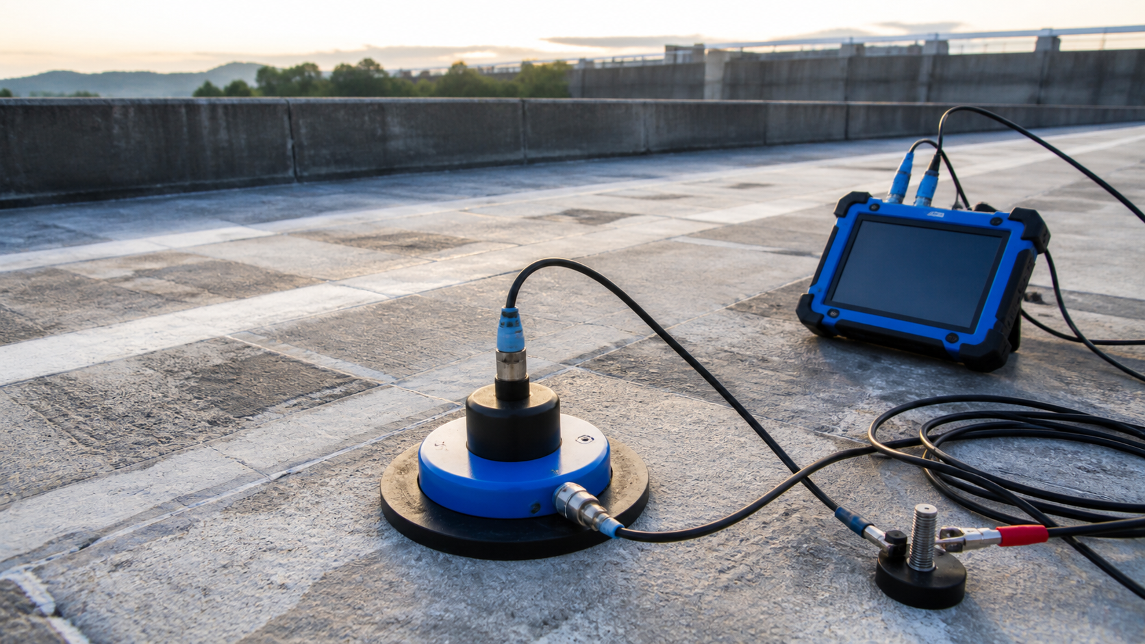
An LPR instrument makes an electrical connection to the reinforcement and places a counter electrode and reference electrode at the concrete surface. It applies a small perturbation around the steel’s corrosion potential, measures the electrical response, and calculates polarization resistance. With an assumed or determined Stern–Geary coefficient and a defensible estimate of the steel area affected by the signal, the result can be expressed as corrosion current density.
ASTM G225-26 is the current field practice for electrochemical measurement of corrosion rate in large concrete structures. It addresses the central field problem: the polarized reinforcement area must be known. The practice describes current confinement using a guard ring and a method based on potential attenuation with distance. ASTM G59-23 provides the underlying polarization-resistance measurement framework, but ASTM G225 is specifically directed to field concrete structures.
The result is an instantaneous electrochemical estimate for the reinforcement layer reached by the measurement. It is not accumulated section loss. Converting a series of measurements into estimated metal loss requires time integration and assumptions that should be stated and justified.
How LPR differs from half-cell potential and resistivity
These methods answer related but different questions:
- Half-cell potential maps electrochemical potential and helps identify the probability or pattern of active corrosion; it does not quantify corrosion rate.
- Concrete resistivity describes how readily ionic current can pass through the concrete and supports interpretation of the corrosion environment; it does not directly measure steel loss.
- LPR estimates corrosion current density at a test location and time, provided the electrical connection, polarized area, surface contact, and calculation assumptions are valid.
A strong program uses these methods together. Start with broad mapping through half-cell potential testing and concrete resistivity testing, then select representative LPR locations across sound, transitional, and distressed zones. LPR should refine the diagnosis rather than become a stand-alone color map.
When the method is useful
LPR can support decisions when an owner needs to compare corrosion activity across a chloride-exposed deck, marine member, parking structure, façade, or other accessible reinforced-concrete element. It can help prioritize intrusive verification, distinguish areas with different current activity, establish a monitoring baseline, or evaluate trends before and after a protection intervention.
The FHWA Long-Term Bridge Performance LPR protocol describes the technique as a rapid, relatively nonintrusive way to estimate instantaneous reinforcement corrosion rate. FHWA also stresses correlation with half-cell potential data and the need for a localized connection to reinforcing steel.
Poor applications include using a handful of readings to estimate whole-building service life, testing epoxy-coated reinforcement as if it were electrically continuous bare steel, applying generic thresholds without checking the governing procedure, or converting a single wet-season survey into decades of predicted section loss.
Plan the survey around the decision
Define the concrete and exposure populations
Separate members by construction phase, concrete mixture where known, exposure, moisture condition, repair history, coating system, geometry, and reinforcement layout. Record leaks, drainage paths, cracks, delamination, previous patches, rust staining, and areas of direct salt or marine exposure. Mixing unrelated populations can obscure the spatial pattern that the survey is meant to reveal.
Map reinforcement before making a connection
Confirm bar location, cover, direction, continuity, and likely layer using drawings and suitable locating equipment. Our guide to rebar locating before concrete repair explains how cover meters and GPR support safer drilling limits. Any local opening or connection must avoid prestressing steel, services, and critical reinforcement damage.
Choose representative locations
Include apparently sound reference areas, zones identified by potential and resistivity mapping, patch perimeters, wet and dry exposures, and visible distress. Do not place every point on the worst-looking concrete. The survey must show transitions and provide enough repeat measurements to distinguish a real pattern from contact or environmental variability.
Set repeatability and escalation rules
Before fieldwork, define what triggers a repeated reading, a second reinforcement connection, a wider grid, intrusive exposure, section-loss measurement, chloride sampling, or structural analysis. A survey is most useful when an anomalous result leads to a pre-agreed next action.
Field QA/QC controls
1. Verify electrical continuity
Confirm that the reinforcement network intended to be measured is electrically continuous. Splices, isolated mats, coatings, cathodic-protection components, repairs, or discontinuous bars can change the current path. Document the connection location, method, bar layer, and continuity checks. Protect the opening after testing with a compatible repair detail.
2. Control surface contact and moisture
The probe needs stable contact with the concrete. Follow the equipment and governing procedure for surface preparation and wetting. Record surface temperature, ambient conditions, visible moisture, recent rain, curing, coatings, and leaks. Moisture changes concrete resistance and corrosion kinetics, so surveys taken under different conditions may not be directly comparable.
3. Establish the polarized area
This is the decisive calculation issue. A small counter electrode on a large reinforcing network does not automatically perturb a known bar area. ASTM G225 addresses this through guard-ring confinement or potential-attenuation measurement. The report should identify the method, geometry, assumed bar diameter and spacing, measured cover, correction approach, and software or equations used.
4. Record raw data and stability checks
Keep open-circuit potential, applied perturbation, measured current, polarization resistance, concrete resistance or compensation data, affected area, assumed coefficient, calculated current density, timestamp, and rejection reason. Repeat unstable points after checking contact, connections, surface condition, and nearby discontinuities. Never retain only the final traffic-light classification.
5. Use competent personnel
The FHWA InfoTechnology LPR guidance notes that the technique requires experienced testing and data processing personnel. Field operators need to recognize bad contact and electrical discontinuity; the engineer needs to evaluate whether the assumed polarized area and electrochemical model are credible for the structure.
Interpretation: rate is not damage
A high measured corrosion current may justify urgent investigation, but it does not reveal remaining bar area. Conversely, a low instantaneous rate does not prove that significant historical loss is absent. Dry concrete can temporarily suppress electrochemical activity even after years of chloride exposure, while wetting can increase a later reading.
Interpret the LPR map beside crack and delamination surveys, cover depth, half-cell potentials, resistivity, chloride and carbonation profiles, exposure history, and direct measurements where reinforcement is opened. Chloride testing before repair helps establish the contamination profile, while exposed-rebar assessment addresses cleaning and actual section-loss decisions once steel is accessible.
Thresholds must come from the selected standard, validated project procedure, and instrument method. Published guidance does not use one universal set of boundaries. ASTM G225-26 is particularly important because earlier field approaches could misstate current density when the polarized area was poorly defined.
From results to repair decisions
Use the combined evidence to divide the structure into engineering zones rather than drawing repair limits from one instrument layer. Possible actions include:
- monitoring a low-consequence, low-activity zone under comparable seasonal conditions;
- expanding electrochemical and chloride mapping around a transition;
- opening representative locations to measure bar condition and verify the diagnosis;
- checking capacity where credible section loss or bond deterioration may affect safety;
- designing patch boundaries with attention to chloride-contaminated adjacent concrete;
- evaluating galvanic anodes, cathodic protection, overlays, membranes, or other protection systems; and
- establishing post-repair baseline measurements and acceptance documentation.
Where localized patches could shift corrosion to adjacent steel, review the role and limitations of galvanic anodes in concrete patch repairs. For widespread active corrosion, cathodic protection may warrant specialist evaluation.
Limitations owners should see in the report
- Instantaneous result: the value changes with moisture, temperature, oxygen availability, and exposure.
- Area uncertainty: current density is only defensible when the polarized steel area is established.
- Electrical access: the method needs a reinforcement connection and suitable continuity.
- Layer sensitivity: the nearest reinforcement layer can shield deeper steel from the measurement.
- Coatings and repairs: impermeable surface systems and electrically isolated reinforcement can prevent or distort testing.
- No direct section-loss measurement: LPR does not replace exposure, dimensional measurement, or capacity analysis.
- Model assumptions: coefficient, resistance compensation, geometry, and equipment processing affect the calculated rate.
Minimum deliverables checklist
- survey objective, populations, grid, and escalation criteria;
- drawings and photographs locating every measurement and steel connection;
- equipment identification, verification records, method, and governing standard;
- reinforcement layout, cover, continuity, and polarized-area method;
- weather, moisture, temperature, surface preparation, and contact conditions;
- raw electrochemical data, calculations, repeats, exclusions, and assumptions;
- co-registered half-cell, resistivity, chloride, delamination, and visual evidence;
- limitations and uncertainty stated beside any classification map; and
- clear recommendations for verification, monitoring, analysis, repair, or protection.
Frequently asked questions
Does LPR show how much reinforcement has already been lost?
No. It estimates instantaneous corrosion current under the test conditions. Historical section loss requires direct measurement or a carefully supported time integration with substantial uncertainty.
Can LPR replace half-cell potential testing?
No. Half-cell mapping efficiently identifies spatial potential patterns; LPR adds rate information at selected locations. The methods are strongest when coordinated with resistivity, chloride profiles, and physical condition data.
Can LPR be used on epoxy-coated reinforcement?
Usually not with the normal single-connection field approach because the coating electrically isolates the steel and disrupts the measurement path. A specialist must verify applicability before testing.
How often should measurements be repeated?
The interval should reflect exposure, consequence, rate variability, and the decision being monitored. Repeat surveys should use comparable locations, equipment procedures, surface preparation, moisture conditions, and documentation.
Does a low reading mean no repair is needed?
No. Low current at one moment may coexist with chloride contamination, previous section loss, delamination, or dry conditions. The engineer must integrate all evidence and check structural consequences.
Turn electrochemical data into an engineering decision
Structural Rehab helps owners scope concrete condition assessments, interpret corrosion evidence, define repair boundaries, and establish practical QA/QC hold points. For project-specific support, visit our consultation page. A defensible LPR survey does not promise certainty from one number; it makes the current corrosion evidence traceable enough to support the next decision.
Engineering note: This article provides general education, not a project-specific testing procedure, durability forecast, structural assessment, or safety determination. Qualified professionals should evaluate existing structures using applicable standards, codes, and site evidence.
Need a professional structural assessment?
Book a consultation with Structural Rehab to evaluate repair priorities, corrosion risks, and rehabilitation options before damage escalates.
Book Consultation