
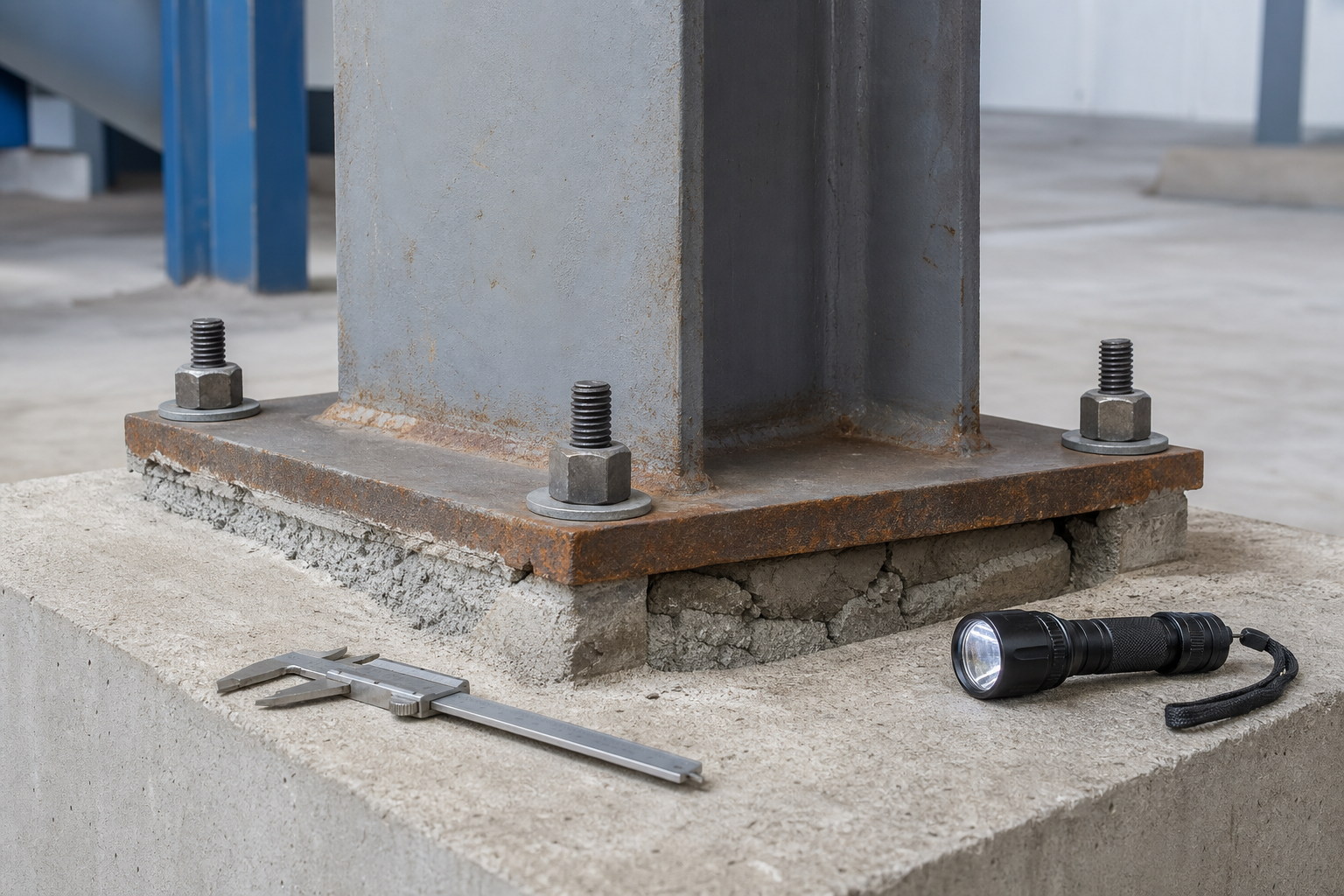
Steel column base plate repair is not simply a matter of removing rust and packing new grout under a plate. The column base is a force-transfer assembly: the steel column, welds, base plate, anchor rods, nuts, washers, grout, and concrete foundation must work together. Deterioration or an improvised repair at any one of those components can change bearing, shear transfer, uplift resistance, stability, and the construction load path.
This guide gives owners, engineers, inspectors, and contractors a practical workflow for assessing corroded or distressed column bases and planning a controlled repair. It focuses on existing building and industrial steelwork. It does not replace project-specific analysis, temporary-works design, or repair drawings.
Why the whole column base must be assessed
A base plate usually distributes column compression into grout and concrete. Depending on the design, anchor rods may resist erection loads, uplift, overturning tension, or shear. Shear may also pass through friction, a shear lug, bearing, or another detailed mechanism. The column-to-plate weld and the concrete anchorage complete the load path.
That is why a cracked grout edge, a corroded nut, or rust at the plate perimeter cannot be interpreted alone. Grout can be visibly damaged yet retain bearing over much of the plate. Conversely, an apparently neat perimeter seal can hide a void, trapped water, section loss, or deteriorated concrete. The repair decision should be based on geometry, material condition, loads, and the intended force-transfer mechanism.
OSHA’s column-anchorage rule is written for steel erection, but it highlights an important safety principle: anchor rods must not be repaired, replaced, or field-modified without approval from the project structural engineer of record. For an existing structure, the responsible engineer should similarly control any cutting, heating, bending, coupling, welding, drilling, or replacement that could affect anchorage.
Recognize conditions that need engineering review
- Visible plate thinning, pitting, lamination, distortion, or uplift at a corner.
- Loose, missing, cracked, bent, necked, or heavily corroded anchor rods, nuts, or washers.
- Loss of thread engagement, damaged threads, inadequate washer bearing, or nuts that cannot be inspected.
- Cracked, debonded, crushed, washed-out, or persistently wet grout.
- Voids under the plate, unsupported edges, excessive stand-off on leveling nuts, or loose shim packs.
- Cracking, spalling, or corrosion staining in the concrete pedestal near the anchorage.
- Column movement, loss of plumb, impact damage, fire exposure, vibration, or signs of fatigue.
- Water entry from washdown, roof leaks, condensation, exterior exposure, or failed perimeter detailing.
These observations do not prove failure, but they justify a defined assessment. If the base supports a heavily loaded, stability-critical, impact-damaged, or nonredundant column, restrict access or loading until the engineer decides whether temporary support is required.
Step 1: establish the original and current load path
Collect structural drawings, base-plate and anchor schedules, foundation details, shop drawings, erection records, previous repair documents, inspection reports, and information about later equipment or occupancy changes. Identify the column’s gravity, shear, uplift, moment, seismic, wind, vibration, and impact demands. Confirm whether the base was intended to act as pinned, partially restrained, or moment-resisting.
Do not infer anchor-rod grade, embedment, or end detail from the exposed diameter. Existing rods may be headed, hooked, threaded into an anchor plate, or post-installed. Material and embedment uncertainty can govern the assessment. Where documents are incomplete, use appropriate nondestructive investigation, selective exposure, testing, conservative assumptions, or a combination.
Also determine the current temporary condition before opening the base. AISC’s Code of Standard Practice notes that a frame erected on shims or leveling nuts can temporarily place steel weight on those localized supports and the anchor rods until grouting is complete. The same principle matters in repair: removing grout can transfer forces into components that were never intended to carry the full in-service load that way.
Step 2: map the condition before disturbing it
Survey geometry and movement
Assign each base a unique identifier. Record column size and orientation, plate dimensions and thickness, anchor pattern, exposed rod diameter, nut and washer arrangement, grout thickness, shim or leveling-nut locations, concrete pedestal dimensions, and access limitations. Use scaled photographs. Measure gaps, plate uplift, grout cracks, column plumb, and any evidence of movement before cleaning or dismantling.
Measure corrosion and steel loss
Remove only enough coating and corrosion product to obtain reliable measurements under an approved procedure. Map base-plate thickness with calibrated direct or ultrasonic measurements where suitable. Measure accessible anchor-rod diameter and pitting, paying particular attention to the first exposed thread, the nut-to-plate interface, and the zone near grout or concrete. Deep localized pits can be more important than uniform surface rust.
Our guide to structural steel section loss repair explains how to turn measurements into an engineering condition map instead of relying on a visual rust grade.
Investigate grout and concrete
Sound the grout where that method is appropriate, inspect exposed edges, and look for voids, cracking, crushing, contamination, moisture, and loss of contact. Small exploratory openings may be justified, but the engineer should approve their location and sequence. Check the pedestal for cracks radiating from anchors, spalls, delamination, and evidence of reinforcement corrosion.
If the concrete condition is uncertain, targeted tests may be needed. See concrete core testing before repair for planning invasive investigation and rebar locating before concrete repair before drilling or exposing embedded components.
Step 3: evaluate every relevant limit state
The engineer should check the base plate, column and welds, anchor rods, nuts and washers, grout or bearing interface, concrete anchorage, pedestal, and foundation using verified dimensions and justified material properties. Relevant checks may include concrete bearing, plate bending, weld strength, rod tension and shear, combined actions, prying, breakout, pullout, side-face blowout, concrete edge effects, shear-lug behavior, and local pedestal reinforcement.
The evaluation should distinguish current capacity from repair-stage capacity. Removing grout, nuts, plate material, or surrounding concrete can create a less stable temporary configuration than either the original or completed condition. A sound sequence defines how gravity, shear, uplift, and moment are carried at every stage.
FHWA guidance for anchored structural supports also warns that excessive exposed rod length between the foundation and leveling nut can introduce unintended bending. Although a building column base is not automatically governed by sign-support guidance, the mechanics are useful: excessive stand-off, plate flexibility, and rod bending must be analyzed, not hidden with cosmetic grout.
Select the repair to match the verified deficiency
Corrosion cleaning and protection
If all components retain adequate capacity and bearing, the repair may focus on cleaning, drainage, sealing details, and a compatible coating system. Prepare plate edges, weld toes, nuts, washers, and other difficult geometries to the specified standard. Avoid trapping water behind a decorative seal. Correct the leak, washdown path, condensation source, or exterior drainage defect that sustained the corrosion.
Use the hold points in our steel coating QA/QC guide for surface preparation, environmental checks, stripe coats, dry-film thickness, cure, and repairs.
Grout removal and replacement
ACI describes cementitious and epoxy grouts as load-transfer materials between a base and foundation. Select grout from the structural, dimensional, exposure, placement, and temperature requirements rather than compressive strength alone. The repair specification should address substrate preparation, plate underside condition, formwork, clearances, mixing, flow or placement method, venting, curing, protection, and acceptance.
Do not remove all existing grout simply because an edge is cracked. First determine how much is unsound and how the column will be supported during removal. Large plates may require a planned placement path or grout holes; AISC notes that grout holes should be considered when the smaller plate dimension becomes large. The completed work should provide verified, continuous load-transfer contact to the extent required by the design.
Anchor-rod, nut, and washer repair
Possible engineered solutions include replacement of accessible hardware, couplers to sound embedded rod material, supplemental post-installed anchors, a revised base plate, welded extensions under a qualified procedure, or foundation reconstruction. None is a universal detail. Available embedment, edge distance, reinforcement conflicts, concrete strength, fatigue, corrosion, installation access, and the ability to develop the new load path all matter.
Heating, straightening, rethreading, or welding an unknown existing rod can reduce capacity or create cracking. OSHA explicitly requires engineer approval for anchor-rod repair, replacement, or field modification during erection. Treat that as a minimum decision discipline for rehabilitation work as well.
Base-plate strengthening or replacement
Plate loss or inadequate stiffness may require cover plates, stiffeners, enlargement, partial replacement, or complete replacement. Added welds can introduce restraint, residual stress, heat effects, and access problems. New anchors or holes must be coordinated with existing reinforcement and foundation edges. The engineer should detail load transfer between old and new steel rather than relying on contact that cannot be installed or inspected.
Temporary support and repair sequencing
The repair drawings should state whether the column must be unloaded, shored, braced, or monitored. They should define the maximum area of grout removed at one time, whether nuts may be loosened, when concrete may be opened, and which components must remain effective. Jacking forces and locations require design because lifting can damage framing, partitions, services, or adjacent foundations.
Do not allow the contractor to improvise a one-corner-at-a-time sequence without analysis. That approach may be reasonable for one base and unsafe for another. The correct sequence is the one that maintains a verified load path and stability through every intermediate state.
QA/QC hold points for column base repair
- Before disturbance: approve the condition map, design assumptions, load restrictions, temporary support, monitoring, and sequence.
- After initial cleaning: verify plate, weld, rod, nut, washer, grout, and concrete measurements against the drawings.
- After opening concealed areas: stop for engineering review if embedment, reinforcement, voids, steel loss, cracking, or concrete condition differs from the design basis.
- Before installing anchors or steel: confirm material certificates, hole locations, reinforcement clearance, drilling method, weld procedure, fit-up, and installer qualifications.
- Before grouting: accept substrate preparation, plate underside, forms, clearances, vents, material condition, mixing equipment, temperature, and curing provisions.
- During grouting: document batch, proportions, mixing time, placement sequence, continuity, leakage, samples, and environmental conditions.
- Before removing support: verify required grout or concrete strength, completed anchorage, accepted welds, monitoring results, and engineer authorization.
- At handover: record as-built details, test results, photographs, coating data, deviations, and the future inspection plan.
The durable repair is not the one that merely hides the gap beneath a fresh grout edge. It is the one that restores a documented load path from column to foundation and leaves inspectable evidence that each component was accepted.
Limitations and owner decisions
This guidance cannot establish capacity or select a repair for a particular structure. Unknown anchor embedment, concealed corrosion, cracked concrete, fatigue-sensitive loading, hazardous coatings, or active movement may require specialized investigation. Emergency stabilization may be appropriate before testing. Owners should also budget for cause correction and follow-up inspection; replacing grout without controlling water exposure often repeats the same deterioration cycle.
For an independent review of a column-base assessment, repair concept, or QA/QC plan, book a Structural Rehab consultation. The site’s practical ebook also covers concrete and steel structures repair and protection for owner planning.
Frequently asked questions
Can damaged grout be patched only at the base-plate edge?
Sometimes, if investigation confirms that the remaining grout is sound, adequately bonded or bearing as required, and the edge defect is localized. A perimeter patch should not conceal internal voids, crushed grout, water paths, or loss of plate support.
Can a corroded anchor rod be welded or extended?
Only through an engineered detail using verified or conservatively assessed material, a qualified procedure, and a load path that develops the required forces. Unknown rod chemistry, poor access, fatigue, heat effects, and inadequate sound length can make welding unsuitable.
Does a loose anchor-rod nut mean the column is unsafe?
Not necessarily, but it requires review. The answer depends on whether the rod resists uplift, moment, shear, or only erection loads; whether other components remain effective; and whether movement, thread damage, grout loss, or plate distortion is present.
Should grout be stronger than the concrete foundation?
Compressive strength is only one selection criterion. Compatibility, bearing behavior, dimensional stability, placement thickness, flow, temperature, exposure, curing, and verified contact are also important. Use the engineer’s specification and the grout manufacturer’s validated installation requirements.
Authoritative references
- OSHA 29 CFR 1926.755, Column anchorage
- AISC 303-22, Code of Standard Practice for Steel Buildings and Bridges
- AISC engineering FAQs: Anchor rods
- AISC engineering FAQs: Base plates
- ACI PRC-351.1-12 (Reapproved 2024), Report on Grouting Between Foundations and Bases
- FHWA Ancillary Structures Inspection Reference Manual
Need a professional structural assessment?
Book a consultation with Structural Rehab to evaluate repair priorities, corrosion risks, and rehabilitation options before damage escalates.
Book Consultation