
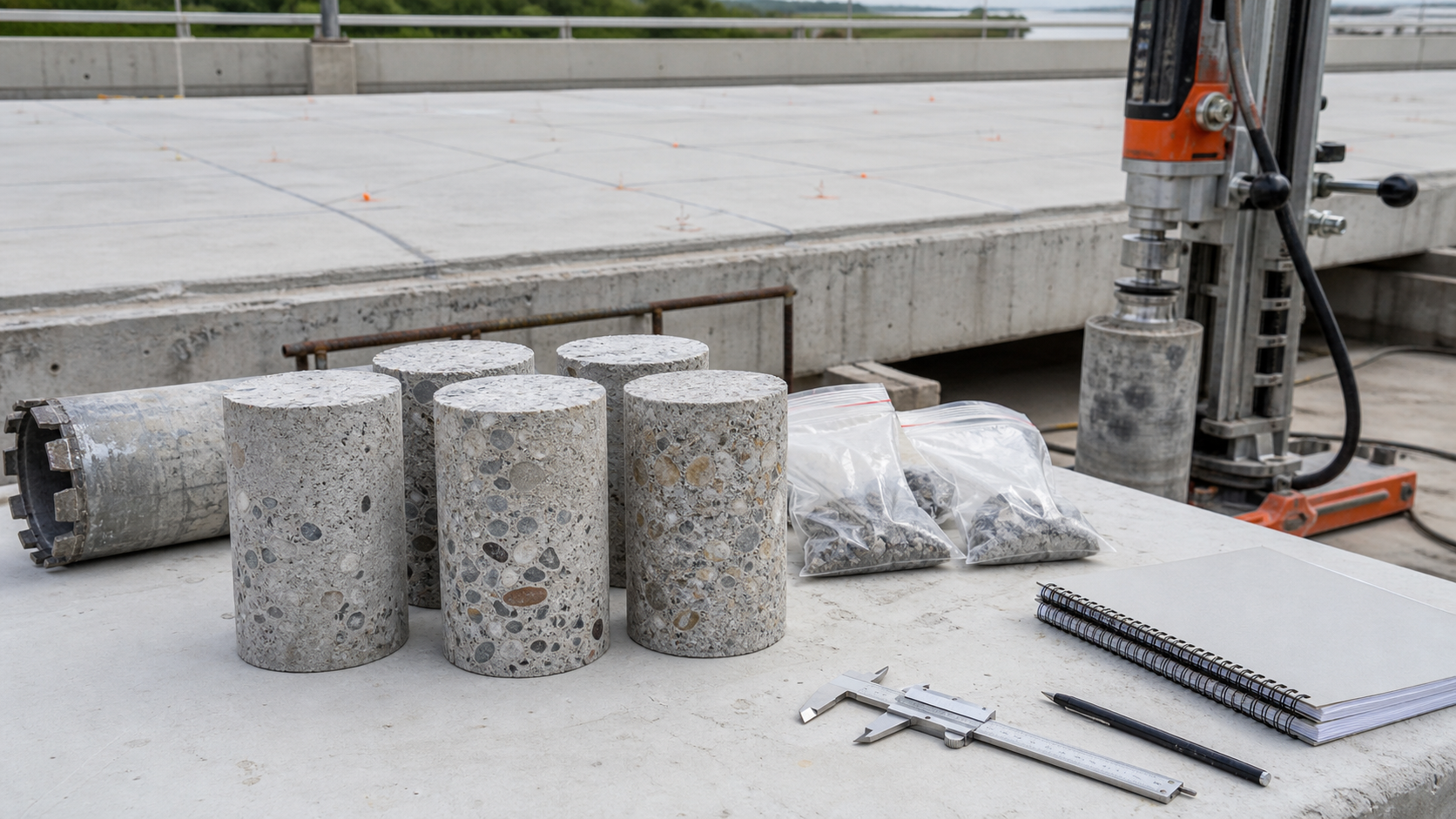
Concrete core testing before repair is not just a way to get a strength number. Done well, it connects visible distress, hidden deterioration, durability exposure, and repair design into one evidence-based plan. Done casually, it can damage useful reinforcement, miss the real deterioration mechanism, or produce lab results that look precise but answer the wrong question.
The safest starting point is a clear engineering question: do we need to verify in-place strength, diagnose cracking or chemical attack, profile chlorides near reinforcement, confirm carbonation or paste quality, or compare sound and distressed zones? Each question can require a different core location, diameter, depth, conditioning method, lab test, and acceptance basis.
When concrete cores are worth taking
Cores are invasive, so they should be used when they change a decision. They are often justified when drawings are incomplete, distress is severe, earlier test results conflict, load rating depends on actual material strength, or repair design needs direct evidence of the concrete below the surface. They can also support durability decisions when chloride contamination, carbonation, alkali-silica reaction, freeze-thaw damage, sulfate attack, or poor consolidation may control the repair strategy.
ASTM C823/C823M-24 frames examination and sampling as part of a planned investigation, not random extraction. The standard notes that sampling can provide material for petrography, chemical analysis, destructive testing, nondestructive testing, and mechanical property evaluation. That is why a core plan should be tied to a distress map, exposure map, structural load path, and the repair choices being considered.
Before coring, use less invasive information to narrow the target. A concrete delamination survey, hammer sounding, cover survey, crack map, moisture observation, and prior repair history help separate representative sampling from avoidable damage. Where drilling could strike bars, ducts, conduits, or embedded plates, perform rebar locating with cover meter or GPR first and mark exclusion zones.
Define the test objective before selecting locations
A good core schedule lists each sample, location, diameter, depth, orientation, intended test, patching method, and reason for taking it. For strength evaluation, locations should represent the structural element being assessed while avoiding reinforcement unless the engineer has allowed it. For deterioration diagnosis, pair samples from damaged, borderline, and apparently sound concrete so the lab can compare what changed.
For corrosion-related repair, one core may not be enough. A chloride result at the surface tells little unless it is related to reinforcement depth, cover quality, exposure, and depth profile. Structural Rehab already treats this in more detail in chloride testing before concrete repair and carbonation depth testing before concrete repair. Core sampling should align with those durability maps so repair limits do not stop at the visible spall.
Strength cores: useful, but easy to overinterpret
ASTM C42/C42M-20 provides standardized procedures for obtaining, preparing, and testing drilled cores from concrete for length, compressive strength, or splitting tensile strength. Its significance notes are important for repair work: core strength is affected by location in the member, orientation, moisture condition at testing, length-to-diameter ratio, consolidation, temperature and moisture history, and the care used during drilling and preparation.
That means a core result is not automatically equal to the original specified compressive strength. It is an in-place sample influenced by construction, service history, damage, and test preparation. For existing structures, the engineer should state how results will be normalized, how outliers will be reviewed, and whether the acceptance basis comes from the governing code, project specification, structural analysis, or a repair code such as ACI 562.
Owners should ask for the lab report to include sample dimensions, length-to-diameter corrections where applicable, moisture conditioning, observed defects, reinforcement interference if any, failure type, test age after coring, and a location plan. A bare table of strengths is not enough for a repair decision.
Petrography: finding the cause, not only the symptom
Petrographic examination is often the step that converts uncertainty into a repair scope. ASTM C856/C856M-20 covers petrographic examination of hardened concrete samples and describes procedures for examining paste, aggregate, cracks, voids, reaction products, and other features. For repair planning, petrography can help distinguish mechanical cracking from shrinkage, freeze-thaw damage, alkali-silica reaction, sulfate-related distress, fire-related paste change, poor consolidation, or incompatible previous repairs.
Petrography should be requested with a project-specific question. For example: “Is the map cracking consistent with ASR?”, “Is there evidence of freeze-thaw distress below the scaled surface?”, “Does the core show microcracking from fire exposure?”, or “Is debonding related to paste condition, surface preparation, or previous repair material?” A generic request for petrography may produce a descriptive report, but a targeted question is more likely to guide repair depth, material selection, and protection strategy.
Chloride and chemical testing from cores
ASTM C1152/C1152M-20 provides procedures for acid-soluble chloride in mortar and concrete. The standard explains that acid-soluble chloride is often equivalent to total chloride, while also noting limits such as sulfide interference and aggregates containing chloride that may not be available for corrosion. For reinforced concrete repair, that nuance matters: a number should be interpreted with exposure, reinforcement depth, corrosion observations, half-cell or resistivity results, and the intended protection system.
Depth-specific samples are usually more useful than one blended sample. If reinforcement is at 45 mm, a chloride profile that separates surface, near-bar depth, and deeper concrete can show whether contamination is shallow, already at steel depth, or distributed through the member. That affects whether patch repair alone is reasonable, whether cathodic protection, galvanic anodes, coatings, or larger removal limits should be considered.
How many cores are enough?
There is no universal number that fits every structure. The right quantity depends on variability, element importance, access, distress patterns, consequence of error, and how the results will be used. A small balcony slab, a transfer girder, a bridge pier cap, and an industrial foundation do not deserve the same sampling plan. The core count should be enough to support the decision being made, but not so large that sampling itself becomes unnecessary damage.
A practical approach is to divide the structure into exposure and condition zones, then sample each zone where the result can affect scope. For strength checks, consider whether separate placements or structural elements need separate data sets. For durability checks, sample near splash zones, leaking joints, previous patch boundaries, sheltered areas, and apparently sound control areas. The final plan should also identify where core holes will be repaired and how temporary structural or waterproofing risks will be controlled.
Field controls that protect the structure
- Mark reinforcement, tendons, conduits, anchors, and embedded plates before drilling.
- Confirm whether coring through compression zones, shear-critical regions, or prestressed elements is prohibited without design review.
- Use water collection and containment where slurry could enter bearings, drains, occupied areas, electrical rooms, or traffic zones.
- Label each core immediately with location, orientation, depth, date, and intended test.
- Photograph the hole, extracted core, fracture surfaces, reinforcement exposure, and patch repair.
- Patch core holes with a repair material compatible with exposure, fire rating, waterproofing, and structural requirements.
Interpreting results for repair design
Core data should be combined with structural analysis, visual inspection, NDE, exposure history, and the owner’s performance objective. A low strength result may require load restriction, strengthening, or replacement, but it may also be localized, damaged by extraction, or not representative of the controlling element. A high strength result does not erase corrosion risk. A clean petrographic report does not remove the need to address leaking joints, poor drainage, or thin cover.
ACI’s repair code portal describes ACI 562 as covering evaluation and analysis, repair design, durability, construction, and quality assurance for existing concrete structures. That broader framework is the right way to use cores: as evidence inside a repair basis of design, not as isolated lab paperwork. The selected repair material still needs to match substrate condition, movement, exposure, and workmanship controls, as discussed in concrete repair material selection and ACI 562-2025 repair code guidance.
Owner checklist before approving coring
- What exact decision will the core result support?
- Has the engineer reviewed drawings, load path, and reinforcement layout?
- Are locations tied to a distress map and exposure map?
- Are core diameter, depth, orientation, and lab tests specified?
- Will the lab report include observations, photos, sample condition, and limitations?
- How will holes be repaired, cured, protected, and documented?
- Who will interpret results and update the repair scope?
Sources
- ASTM C823/C823M-24, Standard Practice for Examination and Sampling of Hardened Concrete in Constructions
- ASTM C42/C42M-20, Standard Test Method for Obtaining and Testing Drilled Cores and Sawed Beams of Concrete
- ASTM C856/C856M-20, Standard Practice for Petrographic Examination of Hardened Concrete
- ASTM C1152/C1152M-20, Standard Test Method for Acid-Soluble Chloride in Mortar and Concrete
- American Concrete Institute, ACI 562 Repair Code portal
- FHWA Long-Term Bridge Performance Program Protocols, concrete material sampling context
FAQ
Does every concrete repair need core testing?
No. Small nonstructural repairs may be designed from visual inspection and surface testing. Core testing is most useful when it will change strength evaluation, deterioration diagnosis, durability planning, or repair limits.
Can core strength be compared directly with original cylinder strength?
Not without engineering interpretation. Core results are affected by member location, orientation, moisture condition, length-to-diameter ratio, extraction damage, and service history.
What is the best test for identifying the cause of concrete distress?
Petrography is often the most useful lab method for identifying distress mechanisms, but it should be combined with field mapping, exposure history, chemical testing, and structural review.
Should chloride samples come from the same cores used for strength?
Sometimes, but the objectives are different. Chloride testing often needs depth-specific powder or slices near reinforcement depth, while strength testing needs properly prepared core specimens.
Who should interpret concrete core test results?
A qualified engineer should interpret the results with the lab, inspection data, drawings, load path, exposure, and repair objective. Lab numbers alone should not define the repair scope.
Need help planning a concrete investigation?
Structural Rehab can help owners and project teams define a practical concrete investigation plan before repair, strengthening, or protection work begins. Book a consultation or download the Structural Rehab concrete and steel repair ebook for a broader planning framework.
Need a professional structural assessment?
Book a consultation with Structural Rehab to evaluate repair priorities, corrosion risks, and rehabilitation options before damage escalates.
Book Consultation