Structural steel repair temporary support release is the controlled handover from a repair-stage load path back to the permanent member, bearing, splice, or connection. It is not simply the moment a jack is lowered or a shore is removed. For a bridge girder, building beam, truss component, or framed connection, release changes forces, deflections, restraints, and sometimes the stability condition of the system. The work must follow an engineer-approved sequence with defined hold points, measurements, communication, and stop-work criteria.
This article focuses on QA/QC for releasing temporary support after an engineered structural-steel repair. It does not design shoring, jacking, member replacement, or connections. A qualified engineer must establish the temporary-works design, load path, release sequence, allowable movements, and acceptance criteria for the actual structure.
Why release is a separate repair hold point
Temporary supports are often needed while a damaged steel segment is removed, a splice is completed, bearings are serviced, or a connection is restored. The permanent repair may look complete while key questions remain unanswered: Are bolts or welds accepted? Is the intended load path available? Are braces and diaphragms installed? Have instruments established a baseline? Has the team confirmed that personnel and equipment are outside the exclusion zone?
FHWA guidance on construction stability emphasizes that temporary supports and jacks can introduce temporary stresses and deflections that require engineering evaluation. The AASHTO/NSBA field-repair guide likewise frames temporary support, removal, repair completion, and support removal as an engineered sequence rather than interchangeable site activities. A release record creates traceability between that design intent and field execution.
Start with the approved release package
Before a crew touches a valve, jack, wedge, or shore, the person responsible for the operation should assemble the current approved documents. The package normally identifies the repair limits; temporary-support layout; jacking points; force or displacement steps; permissible weather, traffic, or occupancy conditions; monitoring points; communications protocol; and contingency actions. It should also identify who may authorize the next step and who may stop the work.
Do not fill missing values with common practice. A similar girder, jack, or repair plate does not establish the reactions or stability of the structure in front of the crew. Changes in bearing condition, corrosion loss, composite action, restraint, construction staging, or support settlement can materially change the operation.
Pre-release field checks
- Confirm the repair matches the latest issued drawings and approved repair disposition.
- Confirm required bolt installation, weld inspection, NDE, coating cure, and any specified waiting periods are accepted.
- Confirm temporary braces, diaphragms, and lateral restraints called for by the plan are in place.
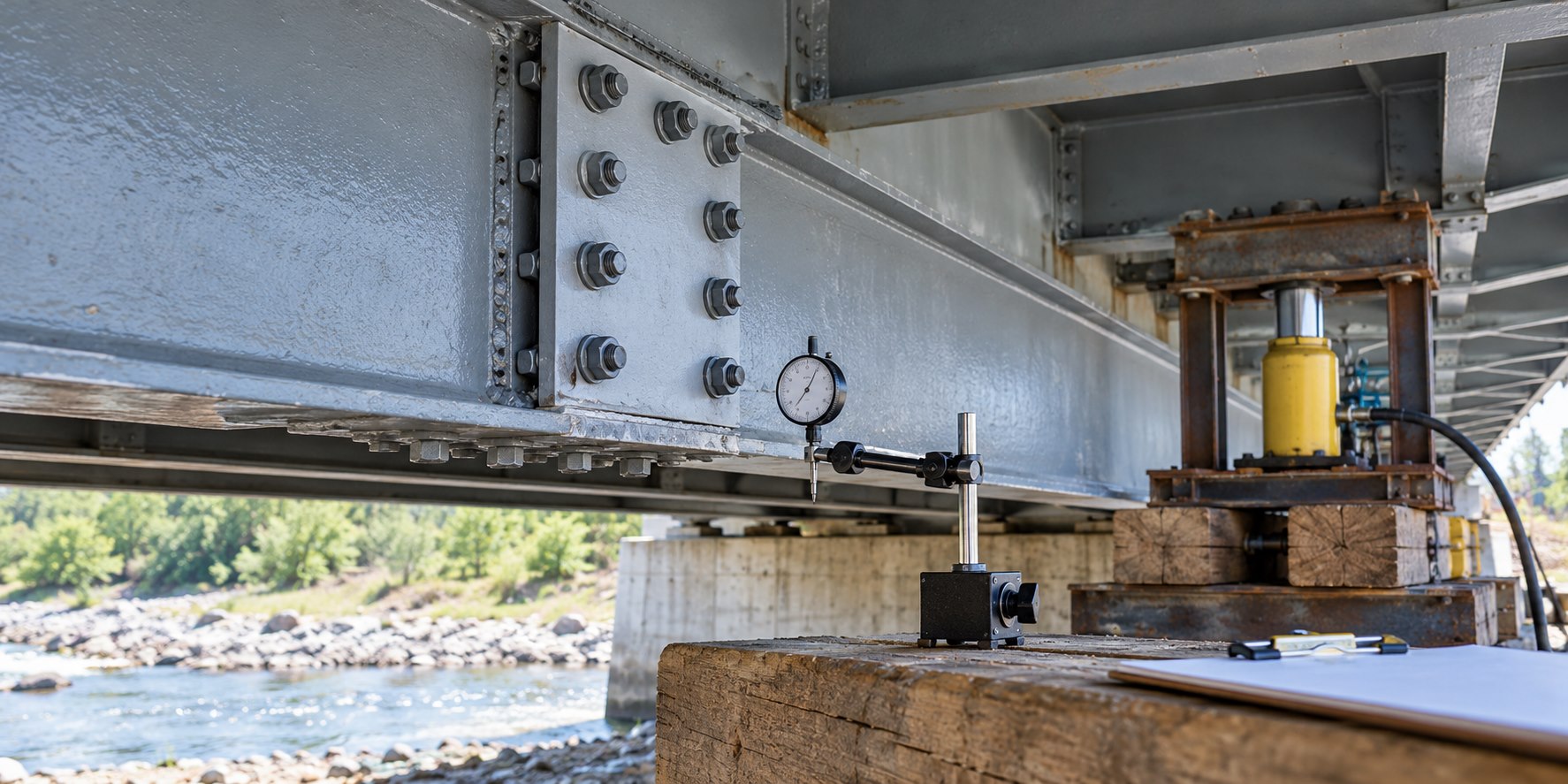
- Verify jack identification, calibration status, hose condition, blocking, bearing surfaces, and independent mechanical safety provisions against the approved procedure.
- Establish a controlled exclusion zone and confirm no person works under a member supported solely by jacks.
- Record initial elevations, gaps, jack readings, and relevant temperatures at the specified locations.
For related connection controls, see our guides to steel repair weld fit-up inspection, direct-tension indicator inspection for repair bolts, and bolt-hole damage assessment.
Turn the sequence into observable steps
A good release sequence has small, unambiguous increments. The engineer may specify load reduction, displacement, or a combination. At each step, the designated observer records the required measurements, compares them with the acceptance limits, and receives explicit authorization before continuing. The field team should not interpret a single smooth movement as proof that the structure has reached its intended final behavior.
Use the units, instrument locations, and acceptance limits in the approved plan. A force reading without a location and time is weak evidence; a dial-indicator value without a baseline or reference point can be misleading. Each release increment needs a recorded instruction, measured response, acceptance decision, and time.
A practical release log
For every planned increment, the log can capture: step number; planned action; person giving the instruction; jack force or stroke before and after; elevation or deflection at each monitoring point; observed movement at bearings, splices, and braces; weather or temperature when relevant; acceptance limit; decision to proceed, hold, or reverse; and signatures or digital acknowledgements. Photographs can help document configuration, but they do not replace measured data or an engineer’s decision.
FHWA’s structural-stability reference manual notes the need to evaluate deflections as temporary supports are removed and to ensure girder stability before removal. That is the reason release monitoring belongs to the repair plan, not only the safety briefing.
What to watch during load transfer
The expected response comes from the engineer’s analysis and the approved sequence. Field personnel should compare actual behavior with the specific limits rather than apply generic tolerances. Potential warnings include an unexpected force redistribution, differential movement between points intended to move together, binding at a bearing, permanent-looking distortion, sudden noise, loss of contact where contact is required, or any change in bracing or support condition.
If the monitored response is outside the plan, stop at the current stable condition, secure the area, preserve readings, and notify the responsible engineer. Do not continue to “see if it settles,” increase the next step, add packing, or modify a connection without an approved disposition. Unplanned re-jacking can create a new load path and obscures the event record.
Release only after the repair can carry its assigned role
Temporary support release is not a substitute for closing repair acceptance. The team should first resolve required inspections and records. For example, a repaired steel member may require accepted field welds, verified bolt installation, completed splice components, and specified protective work before its role in the load path is released. Read our overview of structural steel pack-rust repair for why the remaining parent steel and connection condition still matter after a localized intervention.
Where a temporary arrangement rests on soil, cribbing, falsework, or temporary bents, the foundation and support condition are part of the release decision. FHWA guidance on temporary supports stresses adequate foundation capacity, load distribution, and monitoring for settlement. The article Manual on Use of SPMTs is not a universal repair procedure, but it is a useful primary-source reminder that temporary support conditions need their own design checks and monitoring plan.
Closeout: prove the intended final state
After the final release, verify the final elevations, gaps, bearing condition, member alignment, and any other project-specific criteria. Confirm that temporary supports and equipment are removed only in the approved order. If the engineer requires a hold period or post-release reading, maintain the monitoring arrangement until that check is complete. Then archive the signed release log, instrument records, calibration evidence, inspection reports, photographs, and final engineer disposition with the repair record.
For owner planning, our structural rehabilitation services page explains how to start a scoped assessment and repair discussion. Bring current drawings, inspection findings, repair details, temporary-works information, and any previous monitoring records; they help a qualified team distinguish a local repair from a system-level stability issue.
Limitations
This guidance is an operational QA/QC framework, not a jacking plan or a temporary-works design. It does not establish permissible loads, deflections, release increments, exclusion distances, support capacity, or occupational-safety requirements for a specific project. Those decisions require the responsible engineer, current governing requirements, site conditions, and competent field supervision.
FAQ
Can temporary supports be removed once the repair welds look complete?
No. Visual completion alone does not confirm the repair is accepted, the intended load path is complete, or the release sequence is safe. Follow the approved inspection, monitoring, and authorization steps.
Is a jack pressure gauge enough for release monitoring?
Usually not by itself. The approved plan may require elevations, deflections, gaps, bearing observations, or other indicators. Gauge readings must also be tied to the correct jack, calibration, time, and planned action.
What should the crew do if movement exceeds the predicted value?
Stop the sequence, keep the structure in a stable condition, preserve the readings, isolate the area, and notify the responsible engineer. Do not improvise a correction.
Sources
- AASHTO/NSBA, Guidelines for Field Repairs and Retrofits of Steel Bridges
- FHWA, Engineering for Structural Stability in Bridge Construction Reference Manual
- FHWA, Manual on Use of Self-Propelled Modular Transporters to Remove and Replace Bridges, Chapter 4
- FHWA, Connection Details for Prefabricated Bridge Elements and Systems
Need a professional structural assessment?
Book a consultation with Structural Rehab to evaluate repair priorities, corrosion risks, and rehabilitation options before damage escalates.
Book Consultation