
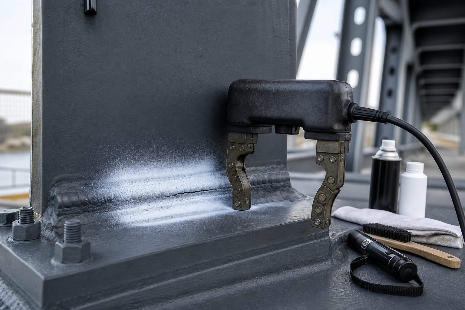
A hairline crack at a weld toe can be easy to miss under ordinary site lighting, especially after corrosion, coating removal, grinding, or a previous repair has changed the surface. Magnetic particle testing (MT) gives a qualified inspector a practical way to search ferromagnetic structural steel for surface and some near-surface discontinuities. It is useful in fabrication, repair hold points, and targeted inspection of in-service bridges, buildings, supports, and industrial structures.
MT is not a stand-alone verdict on weld quality. The governing design or welding code, project specification, approved procedure, and engineer’s evaluation determine what must be examined and what is acceptable. The test reveals relevant indications; it does not by itself prove remaining capacity, fatigue life, crack depth, or fitness for service.
What magnetic particle testing can find
MT magnetizes the steel and applies fine ferromagnetic particles to the test surface. A discontinuity that interrupts the magnetic field can create flux leakage. Particles gather at that leakage field and form a visible indication. ASTM E709-21 describes dry and wet techniques for detecting cracks and other discontinuities at or near the surface in ferromagnetic materials. The method is especially responsive to elongated discontinuities such as cracks when the magnetic field crosses them at a favorable angle.
Typical structural applications include weld toes, weld ends, attachments, flame-cut edges, drilled or punched details, repaired areas, and fatigue-sensitive locations. FHWA identifies steel girders, truss members, sign supports, and light poles as common bridge and ancillary-structure applications. MT may be used during fabrication or on an in-service structure where service loading may have produced cracking.
What MT does not establish
- It does not reliably characterize deeply embedded discontinuities.
- It does not measure crack depth or remaining steel section.
- It does not apply to aluminum or non-ferromagnetic austenitic stainless steel.
- It does not replace visual inspection before, during, and after welding.
- It does not supply acceptance criteria. ASTM E709 expressly leaves acceptance to the applicable code, specification, or agreement.
- It does not convert a local result into a structural capacity conclusion.
Where internal weld soundness matters, another method may be required. AISC explains that method selection depends on the anticipated discontinuity, the method’s detection capability, and cost. Ultrasonic or radiographic examination can be appropriate when internal soundness is important; the engineer must define the required method, extent, technique, and acceptance standard.
Start with an inspection plan, not a yoke
A defensible program begins by identifying why the location is being examined. Is the objective to verify removal of a known crack, inspect a new repair weld, investigate a fatigue-prone detail, or sample workmanship? That decision controls the examination boundaries, surface preparation, timing, sensitivity, documentation, and response to relevant indications.
For an existing structure, first review drawings, load paths, fatigue details, previous inspection reports, coating history, and earlier repairs. Combine this with a close visual survey. The site’s broader guide to welded steel connection repair explains why crack cause, restraint, access, welding procedure, and repair sequence must be resolved before simply depositing new weld metal.
Define the governing requirements
State the applicable edition of the structural welding code and any owner-specific provisions. AWS D1.1/D1.1M:2025 covers structural steel welding, inspection, and acceptance, and its 2025 revision added provisions for MT and penetrant testing. Bridges or other specialized structures may invoke a different AWS code or agency specification. Do not transfer acceptance limits from one code, weld type, loading condition, or project to another without engineering review.
The written plan should identify the welds and adjacent base metal to be examined, percentage or length of examination, technique, particle system, lighting conditions, timing relative to welding and cooling, surface condition, personnel qualifications, acceptance criteria, reporting fields, and escalation rules. It should also define whether a repeat examination is required after grinding, excavation, rewelding, or final dressing.
Surface preparation controls reliability
Heavy scale, loose rust, weld spatter, oil, dirt, and rough coating can prevent particles from moving freely or can create confusing nonrelevant indications. Prepare the surface to the approved procedure without grinding away evidence or changing the geometry before the condition is documented. If coatings remain, verify that their thickness and magnetic properties are compatible with the procedure and required sensitivity.
Preparation near corrosion-damaged details should be coordinated with thickness and section-loss assessment. MT may locate a crack, while an ultrasonic thickness survey can map remaining thickness. Neither substitutes for the engineer’s analysis of net section, local buckling, connection behavior, or fatigue demand. For coating removal and restoration, integrate the work with the site’s guidance on steel surface cleanliness and appropriate surface profile measurement.
Field technique and essential controls
A portable electromagnetic yoke is common for field weld inspection. Dry visible particles can suit rough surfaces and outdoor work; wet visible or fluorescent systems can offer different sensitivity and viewing requirements. The approved procedure should match the material, surface, geometry, environment, and discontinuities of interest. Product instructions and safety data also govern handling, ventilation, flammability controls, and cleanup.
Use more than one field direction
Detection is strongest when a discontinuity is approximately perpendicular to the magnetic field. A crack nearly parallel to one field direction may give a weak or missed indication. FHWA training guidance therefore illustrates positioning the yoke in two generally perpendicular directions when evaluating a weld. The examination grid must preserve the suspected crack orientation, not let one convenient yoke position define the result.
Verify equipment performance
Confirm equipment condition, current type, pole spacing, field adequacy, particle condition, and lighting using the checks required by the approved procedure. A yoke lift test may be specified, but the required value depends on the applicable standard, current type, and pole spacing; it should not be copied from an unrelated project. Fluorescent examination also requires controlled ultraviolet and ambient-light conditions and suitable eye adaptation.
Inspectors should be qualified and certified as required by the contract. ASTM E709 points to recognized personnel-qualification routes while allowing the purchase order or contract to specify the applicable system. Equipment calibration records do not replace technique demonstrations, inspector competence, or supervision.
Interpret indications before calling defects
An indication is particle accumulation that requires interpretation. Geometry changes, weld ripples, sharp corners, permeability changes, arc strikes, surface scratches, and residual magnetism can create nonrelevant or false patterns. Clean and re-examine questionable areas, adjust field direction, and use another suitable method when needed. Record the original condition before grinding or excavation destroys it.
Relevant indications must be evaluated against the governing acceptance criteria, not against the inspector’s intuition. If a crack is confirmed, establish its extent and probable cause before repair. A fatigue crack may extend beyond the visible indication or recur if the stress range, detail category, distortion, vibration, or restraint remains unchanged. Review related guidance on structural steel section-loss repair and controlled heat straightening when deformation or material damage is also present.
Repair verification and QA/QC hold points
A crack-removal sequence normally needs hold points. First document and mark the indication. Then remove material by the engineer-approved method while protecting sound steel. Re-examine the excavation to confirm complete removal before welding. Verify joint geometry, preheat, consumables, welding procedure, welder qualification, and access. After welding and the required cooling or delay period, complete visual inspection and the specified NDT. Restore the protective coating only after acceptance.
- Before examination: confirm location, identity, surface condition, code, procedure, and inspector qualification.
- During examination: record equipment, consumables, field directions, pole spacing, lighting, and environmental constraints.
- At an indication: photograph it with scale and location reference; classify it before removal.
- After excavation: repeat MT or the specified method to verify the discontinuity is gone.
- After repair: apply the required inspection method and acceptance criteria at the specified time.
- At closeout: link the report to drawings, repair records, coating restoration, and future monitoring.
Coating closeout needs its own controls. Confirm environmental conditions, surface preparation, dew-point margin, stripe coating where specified, and final thickness. Structural Rehab’s article on dry-film thickness testing provides a complementary checkpoint.
Owner’s specification checklist
- Name the governing code, edition, and project specification.
- Identify exact welds, adjacent zones, examination extent, and timing.
- Define the MT technique, surface condition, sensitivity checks, and viewing conditions.
- Require qualified personnel and traceable equipment and consumable records.
- State acceptance criteria and who has authority to interpret and accept results.
- Require two suitable field directions unless the approved technique justifies otherwise.
- Set hold points before excavation, before rewelding, after repair, and before recoating.
- Require mapped, photographed reports that distinguish relevant, nonrelevant, and false indications.
- Define the engineering response to confirmed cracks, including cause analysis and monitoring.
Frequently asked questions
Can magnetic particle testing find cracks through paint?
Sometimes a qualified procedure permits examination through a thin, well-adhered coating, but coating thickness, condition, and magnetic properties can reduce sensitivity. The governing procedure must define what is allowed; do not assume a painted surface is acceptable.
Is MT better than dye penetrant testing?
Neither method is universally better. MT can reveal surface and some near-surface discontinuities in ferromagnetic materials. Penetrant testing is limited to discontinuities open to the surface but can be used on many nonporous nonmagnetic materials. Select the method around material, expected flaw, geometry, surface condition, code, and access.
Does a visible MT line mean the weld must be rejected?
No. It is an indication that must be interpreted, classified, and evaluated using the applicable acceptance criteria. Some patterns are nonrelevant or false. Confirmed cracks, however, normally require prompt engineering review and controlled disposition.
Can MT prove a repaired member is structurally safe?
No. MT can provide evidence about detectable discontinuities in the examined area. Structural safety also depends on loads, crack extent, section loss, material properties, connection behavior, repair design, workmanship, and future service conditions.
Authoritative references
- ASTM E709-21, Standard Guide for Magnetic Particle Testing
- AWS D1.1/D1.1M:2025-AMD1, Structural Welding Code—Steel overview
- AISC Welding Inspection and Nondestructive Examination FAQ
- FHWA InfoTechnology: Magnetic Particle Testing
- FHWA HMEC Module C Welding Laboratory Manual
Plan the inspection around the decision
Structural Rehab can help owners define targeted steel-weld inspection, connect NDT findings to engineering assessment, and develop repair hold points that preserve evidence and control risk. Book a structural rehabilitation consultation to discuss a specific structure. You can also use our repair resources and ebook as planning aids; they do not replace project-specific engineering, testing, or code review.
Need a professional structural assessment?
Book a consultation with Structural Rehab to evaluate repair priorities, corrosion risks, and rehabilitation options before damage escalates.
Book Consultation