
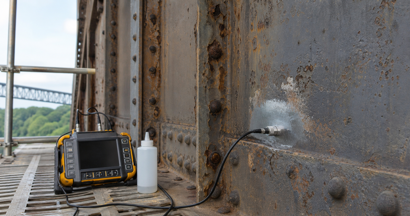
Ultrasonic thickness testing gives engineers a practical way to measure remaining steel thickness when corrosion, access, or geometry makes calipers unreliable. The method can work from one accessible face, but a displayed number is not automatically a design value. A defensible survey needs a written measurement plan, suitable surface preparation, calibrated equipment, repeatable locations, and engineering interpretation.
This guide explains how owners, engineers, and inspectors can use ultrasonic thickness testing for corroded structural steel without confusing an instrument reading with a complete condition assessment.
What ultrasonic thickness testing measures
A contact pulse-echo thickness gauge sends an ultrasonic pulse into the steel and measures the round-trip travel time of the reflection from the back surface. With the correct sound velocity, the instrument converts that time into thickness. ASTM E797/E797M-21 provides the active practice for manual ultrasonic pulse-echo contact thickness measurements. FHWA describes the technique as a field-ready method for determining section loss in plate-like steel bridge components.
The key output is local remaining thickness at the probe location. It does not directly establish member capacity, corrosion rate, crack absence, or the condition of inaccessible layers. Those conclusions require the original dimensions, the structural model, the deterioration pattern, and sometimes other examination methods.
When UT adds value
Visual inspection should first locate rust scale, pack rust, perforation, distortion, coating failure, moisture traps, and suspect load-path details. Ultrasonic thickness testing then adds quantitative evidence where direct mechanical measurement is impractical. Common applications include girder webs and flanges, gusset plates, box sections, tubular members, steel piles, tanks associated with structures, and ancillary supports.
FHWA specifically recommends UT thickness measurement when corrosion on single-plate gusset connections cannot be adequately quantified visually. It is also useful for establishing baseline grids that can be relocated during later inspections. For a broader decision framework, see our guide to structural steel section-loss repair.
Plan the survey before taking readings
Define the engineering question
State whether the survey is intended to screen a large area, map a known corrosion zone, confirm a repair quantity, support load rating, or monitor change. The purpose controls grid spacing, access, documentation, and the number of repeat measurements. A coarse screening grid may miss a narrow pit; an extremely dense grid may add cost without improving the engineering decision.
Establish the reference thickness
Section loss is the difference between a justified reference thickness and the measured remaining thickness. Use drawings, mill records, specifications, unaffected comparison zones, or other verified evidence. Do not assume that nominal catalogue thickness equals the as-built thickness everywhere. Record the basis and uncertainty.
Choose repeatable locations
Lay out a grid from permanent, documented reference points. Concentrate readings at drainage paths, horizontal ledges, crevices, lower flange edges, bearing zones, connection interfaces, splash zones, and transitions between sound and deteriorated steel. Photograph and sketch the grid so another technician can reproduce it. FHWA guidance for gusset plates emphasizes retaining locations and dimensions in the bridge file.
Field procedure and QA/QC
Prepare only what is necessary
Remove loose scale, debris, and poorly bonded coating at the test spot as permitted by the owner. The probe needs stable acoustic contact. Heavy roughness, deep pits, curvature, and residual scale can scatter sound or prevent a reliable back-wall echo. Coordinate coating disturbance, lead-paint controls, containment, and recoating before work begins. The steel surface cleanliness guide explains why preparation requirements must be specified rather than improvised.
Use the correct probe and couplant
Select the transducer for the expected thickness, curvature, surface condition, temperature, and instrument capability. Apply a compatible couplant in a controlled manner. Small-diameter or dual-element probes may help on localized corrosion, but their response and limitations must be understood. Hot surfaces require equipment and procedures rated for the temperature; ASTM E797/E797M defines its own application limits.
Calibrate and verify
Calibrate with traceable reference blocks or steps that bracket the expected measurement range and match the material response as closely as practical. Confirm sound velocity, zero compensation, and any coating mode before collecting data. Perform verification checks at the start, after a significant setup change, periodically during the shift, and at the end. If a verification check falls outside the project tolerance, quarantine the affected data until it is evaluated or repeated.
Require stable, repeatable readings
Take multiple readings at suspect points, repositioning the probe slightly while staying within the defined location. A value that changes sharply with probe pressure or position may reflect roughness, poor coupling, geometry, a coating interface, or a real pit. Do not simply record the lowest flickering display. Save waveforms when the instrument permits and the consequence of the decision warrants it.
The inspection grid must preserve the corrosion pattern, not average it out of existence. Record individual credible minima, typical readings, rejected readings with reasons, and inaccessible spots. This unique discipline keeps a convenient mean value from hiding a localized capacity concern.
Turn readings into an engineering map
Report coordinates, component face, original or reference thickness, measured thickness, calculated loss, surface condition, coating status, probe, instrument, calibration blocks, operator, date, temperature where relevant, and uncertainty or limitations. Use a plan, elevation, or member sketch with a consistent color scale. Keep raw values available rather than presenting only contours.
Compare the mapped loss with the load path and limit states. The same thickness loss can have different significance in a slender web, a net section at a connection, a compression element, or a low-stress cover plate. Where corrosion affects bolts, welds, or connection geometry, coordinate the findings with the bolted connection repair and welded connection repair guidance.
Limitations that must appear in the report
- Multilayer assemblies: ordinary contact UT may measure only the plate coupled to the probe and may not characterize corrosion between nested plates. FHWA identifies this as an important gusset-plate limitation.
- Rough or deeply pitted steel: unstable coupling and scattering can make a single numerical reading misleading. Supplement with pit gauges, profiling, alternative probes, or other NDE as appropriate.
- Coatings: some gauges can compensate for coatings, but the mode must be validated. Coating thickness can otherwise bias the apparent steel thickness.
- Geometry: edges, curvature, laminations, weld profiles, and nearby fasteners can disrupt the sound path.
- Cracks and weld flaws: a basic thickness survey is not a substitute for a qualified flaw-detection examination. Use appropriate UT, phased-array UT, magnetic particle testing, or another specified method.
- Sampling: thickness between grid points remains unknown. Grid density must match the corrosion morphology and decision consequence.
FHWA’s UT thickness-measurement resource notes the one-sided access advantage while also stressing surface preparation and trained operators. Its underwater inspection manual further warns that very rough or badly pitted steel may require an alternative such as a pit gauge.
From measurement to repair decision
First determine whether immediate controls are needed: load restriction, shoring, access exclusion, temporary stabilization, or expedited analysis. Then model the actual remaining section using a conservative, documented representation of the mapped loss. Repair concepts may include plate addition, member replacement, connection reconstruction, drainage correction, debris removal, or coating renewal. Do not cover active traps or pack rust without resolving their mechanism.
After structural work, specify surface preparation and coating QA/QC. Useful companion checks include soluble-salt testing, surface-profile measurement, and dry-film thickness verification. Preserve selected UT points as monitoring baselines when future exposure remains possible.
Owner’s acceptance checklist
- The inspection purpose, components, grid, and inaccessible areas are defined.
- The reference thickness and its evidence are stated.
- Technician competence, instrument, probes, blocks, and calibration records are documented.
- Surface preparation and coating disturbance controls are approved.
- Repeatability criteria and responses to unstable readings are defined.
- Raw data, photographs, sketches, and mapped results are delivered.
- Multilayer, pitting, geometry, coating, and sampling limitations are explicit.
- A qualified engineer converts the measurements into capacity, repair, and monitoring decisions.
Frequently asked questions
Can UT measure steel from one side?
Yes. Contact pulse-echo thickness measurement normally needs access to only one face and uses the reflection from the opposite surface. The back surface still needs to produce a resolvable echo.
Can a gauge read through paint?
Some instruments and modes can compensate for coatings, but capability depends on the system, coating, thickness range, and calibration. Validate the setup rather than assuming the displayed value excludes paint.
Does the lowest reading define member capacity?
Not by itself. The engineer must assess whether the reading is valid, how much area it represents, where it lies in the load path, and which limit state governs.
How close should the measurement grid be?
There is no universal spacing for every structure. Use closer spacing where corrosion is localized, consequences are high, or gradients are steep; justify wider spacing for uniform screening zones.
Can ordinary UT assess corrosion between two gusset plates?
Not reliably in every multilayer configuration. Standard thickness UT may characterize only the contacted plate. The inspection plan should identify layered details and select supplementary methods or conservative evaluation.
Get an evidence-based repair plan
Structural Rehab can help owners turn inspection measurements into a scoped engineering assessment, repair strategy, and QA/QC plan. Book a consultation to review the structure, access constraints, testing objectives, and decision thresholds. Testing and repair must be designed and supervised by qualified professionals for the specific structure.
Authoritative sources
- ASTM E797/E797M-21, Standard Practice for Measuring Thickness by Manual Ultrasonic Pulse-Echo Contact Method
- FHWA InfoTechnology: Ultrasonic Testing (Thickness Measurement)
- FHWA Technical Advisory 5140.31: Inspection of Gusset Plates Using NDE Technologies
- FHWA Underwater Bridge Inspection Reference Manual
- FHWA Ancillary Structures Inspection Reference Manual
Need a professional structural assessment?
Book a consultation with Structural Rehab to evaluate repair priorities, corrosion risks, and rehabilitation options before damage escalates.
Book Consultation