A durable concrete repair must respect every active joint or moving crack that reaches the repair boundary. When a partial-depth patch bridges a working joint, the new repair can become a restraint point: movement that the original joint was meant to accommodate is redirected into the patch edge. This article gives owners, engineers, contractors, and inspectors a practical concrete repair joint interface QA/QC workflow for preserving the joint, rebuilding a sealant reservoir, and documenting acceptance.
It applies to engineered pavement, deck, and slab repairs where the repair documents call for a joint insert, resealing, or both. It does not replace the repair design, the project specifications, or an evaluation of distress that might be caused by load transfer, drainage, reinforcement corrosion, or a deeper structural problem.
Why the joint interface deserves its own hold point
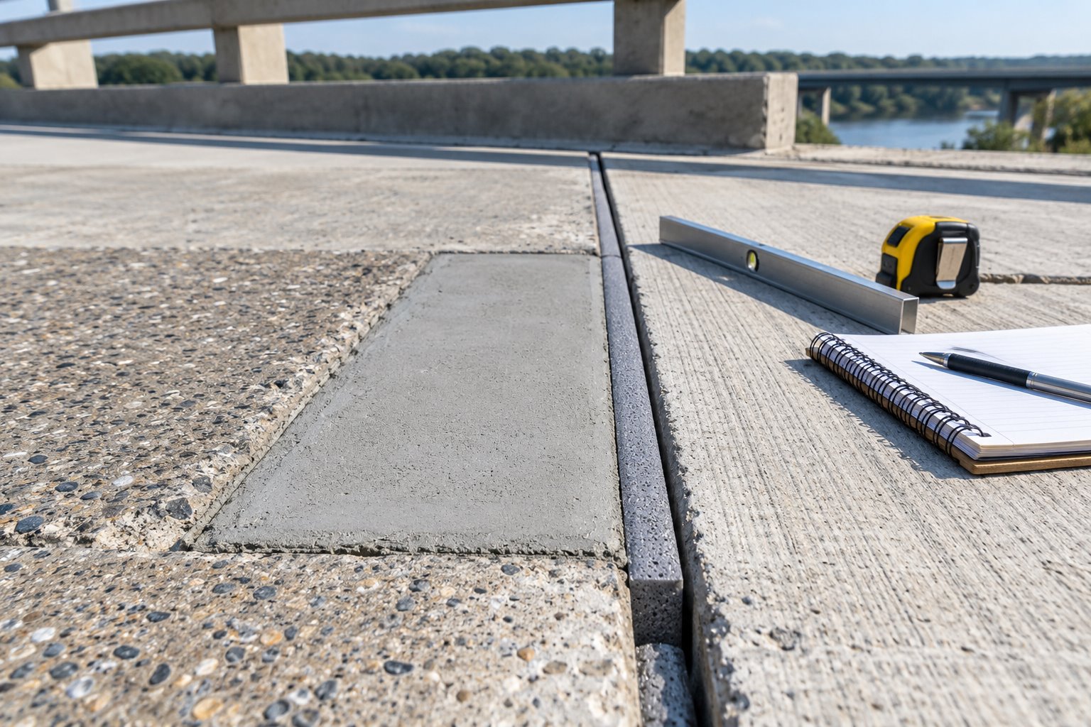
A patch restores deteriorated concrete; it is not automatically a movement joint. FHWA notes that a partial-depth repair adjoining a working joint or full-depth crack needs a compressible insert so the repair does not bear on adjacent concrete. The insert also creates a cleaner face for later resealing. Without that separation, thermal or service movement can create point bearing, pop-outs, debonding, or an early crack at the patch perimeter.
The interface is easy to lose in a busy repair sequence. Removal crews may see a narrow joint as an inconvenient gap; finishers may pull fresh material across it; and a sealant crew may arrive after dust, moisture, or curing residue has entered the reservoir. A named hold point turns these small decisions into a controlled sequence.
Start with an engineered condition decision
Before selecting an insert, sealant, or reservoir geometry, establish what the line actually is. Review plans, joint schedules, previous repairs, distress mapping, and observed movement. Confirm whether the feature is an expansion joint, contraction joint, construction joint, designed crack, or an unintended crack that requires a different repair method. Record its location, orientation, condition, and relationship to the proposed removal limits.
Do not assume every visible crack should be converted into a joint, and do not fill a designed movement joint with repair mortar. If deterioration extends deeper than the intended repair, reaches reinforcement, involves loss of support, or suggests lock-up or load-transfer distress, pause for the engineer’s disposition. The field team should not change a partial-depth repair into a full-depth or structural repair by improvisation.
Coordinate the repair boundary
Mark the approved limits before cutting. Keep the boundary square or rectangular where the repair system requires it, and preserve the intended joint line through the repair. For related removal controls, use the project procedure and the site’s concrete repair saw-cut boundary guidance. Photograph and reference the station, grid, or room location so the final QA record can be traced to the repair map.
Pre-placement QA/QC: the joint-preservation checklist
Hold the repair for inspection after removal and before bonding or placing material. The inspector and contractor should confirm the following items against the approved repair procedure:
- Sound substrate: removal has reached the required sound material without damaging adjacent concrete or reinforcement.
- Joint continuity: the working joint or designated crack is visible and has not been filled with debris or loose repair material.
- Approved insert: the compressible insert type, depth, width, and termination match the repair details; it is not a substitute for the design.
- Clean interfaces: dust, laitance, standing water, oil, curing residue, and loose particles are removed in the manner the repair system permits.
- Moisture condition: substrate moisture is compatible with the bonding and repair materials, not judged from appearance alone.
- Release record: the engineer or authorized inspector accepts the condition before placement.
Use the same disciplined substrate checks that protect bond elsewhere in the repair. The site’s surface-profile QA/QC workflow can help document the prepared patch surfaces, while the joint face and reservoir receive their own acceptance criteria.
Place the patch without locking the joint
Install the insert only as specified and keep it stable while the repair material is placed, consolidated, and finished. Its job is separation: it should stop fresh repair material from migrating into the joint and prevent the patch from carrying compression across a moving interface. Do not make field changes to its depth or material merely because it is difficult to hold in position.
Consolidate repair material enough to eliminate voids at the old-to-new concrete interface, but do not displace the insert or contaminate the joint line. Finish to the required profile without feathering material into the reservoir. Then protect the joint from foot traffic, curing overspray, rain-borne debris, and traffic until the next operation. Record the repair-material batch, placement time, ambient conditions if required, and the person who checked the joint line.
Curing is not an afterthought. Premature moisture loss can contribute to shrinkage and debonding in small repairs. Follow the material data, contract requirements, and the engineer’s procedure. A curing method that leaves residue in the future sealant bond area should be addressed before it is used, not discovered during resealing.
Rebuild and inspect the sealant reservoir
After the patch has reached the required condition for the next operation, form or saw the sealant reservoir to the approved joint detail. This is not a generic “fill the gap” activity. The specified reservoir dimensions, surface preparation, primer requirements, backup material, bond breaker, and sealant all work together. Use only the project’s approved system and installation limits.
FHWA guidance emphasizes clean, dry joint faces and preparation that provides the intended sealant shape. A practical inspection sequence is:
- Verify the repair has not bridged the joint and that the reservoir follows the intended alignment.
- Check the faces for sound concrete and remove saw residue, dust, loose material, moisture, and incompatible contaminants as required.
- Confirm the backup material or bond breaker is located at the approved depth and has not climbed into a sealant bonding face.
- Apply primer only where the approved system requires it, within its stated application window.
- Place the sealant continuously, tool it as required, and inspect for voids, adhesion loss, contamination, or an unintended three-sided bond.
- Document the material lot, installation conditions, test or inspection results, repairs made, and acceptance authority.
Surface sealing may reduce water and contaminant entry in an appropriate nonmoving crack, but it does not restore structural capacity or resolve a moving joint. Where the line is active, selection and detailing belong to the engineer and the project specification.
Acceptance records that are useful later
Close the repair with evidence that someone can interpret months later. Link the repair identifier to the condition survey, approved repair detail, pre-placement photos, insert verification, repair-material record, curing record, reservoir inspection, sealant batch, and final photos. A post-repair sounding check may help screen the surrounding patch condition; use the site’s post-repair sounding acceptance guide without representing sounding as a complete structural evaluation.
For multi-repair programs, map recurring failures by joint type, exposure, material, and crew sequence. That evidence can show whether the corrective action belongs in drainage, detailing, repair limits, materials, or installation controls.
Limits and escalation triggers
Escalate rather than proceed when the joint cannot be identified, the repair would alter a structural load path, reinforcing steel or dowels are unexpectedly exposed, movement appears larger than assumed, the substrate remains unsound beyond the planned limits, or the specified joint geometry cannot be achieved. Also escalate if the repair detail conflicts with the manufacturer’s system requirements. The correct response may be a revised repair design, not a more aggressive field fix.
For project-specific help with assessment, repair scope, sequencing, and QA/QC documentation, Structural Rehab can support a coordinated engineering and construction-review discussion through our structural rehabilitation services.
FAQ
Can repair mortar fill a working concrete joint?
Not when the joint is intended to move. Repair mortar generally cannot accommodate the same movement as a designed joint. Preserve the joint with the approved insert and resealing detail, or obtain an engineer’s revised direction.
Is a compressible insert the same as sealant backer material?
They can serve different functions and are not interchangeable by default. The repair detail should identify the material, location, and purpose. Use only the approved system.
When should a joint be resealed after a patch?
After the patch and joint faces meet the approved readiness conditions and the sealant system’s requirements. The exact timing depends on the repair material, curing process, weather, and project specifications.
Sources
- FHWA: Partial-Depth Repairs—Construction
- FHWA: Partial-Depth Repairs—Generic Guide Specification
- FHWA: Concrete Pavement Preservation Guide
- TxDOT Concrete Repair Manual: Crack Repair—Surface Sealing
A preserved joint is a movement detail with documented intent, not an accidental gap in a concrete patch.
Need a professional structural assessment?
Book a consultation with Structural Rehab to evaluate repair priorities, corrosion risks, and rehabilitation options before damage escalates.
Book Consultation