Structural steel repair welding can change geometry even when every weld deposit appears sound. Heat, restraint and shrinkage can pull a flange, rotate a connection, close a gap or introduce a local eccentricity. A steel repair weld sequence distortion control plan turns that risk into measurable hold points before the first production weld is made.
This article is a field QA/QC framework for an engineer-designed repair. It does not authorize a contractor to change a weld procedure, alter a load path, add restraint, heat-straighten a member or accept out-of-tolerance geometry without the engineer of record’s written direction.
Why welding sequence belongs in the repair plan
Weld metal contracts as it cools. In a repair, that contraction occurs in a member that may already carry dead load, have residual stress, or be constrained by adjacent steel, temporary works and attachments. The result can be angular change, sweep, camber change, local buckling, fit-up loss or unintended force in the repaired detail.
The AASHTO/NSBA field-repair guideline identifies heat control, restraint and mapped weld sequencing as ways to manage distortion and cautions that too much external restraint can create its own fracture risk. FHWA’s Bridge Welding Reference Manual likewise illustrates balancing welds and staging passes so an assembly shrinks in a controlled manner. Those principles are useful for buildings and industrial structures too, but the applicable project documents and governing welding code control.
Start with an engineered distortion-control brief
Before work starts, the repair team should convert the approved drawings and WPS into a concise, job-specific brief. Do not use a generic sequence from another detail. The brief should identify:
- the member, repair limits, material identification and affected load path;
- the approved WPS, weld symbols, pass sizes, preheat/interpass limits and consumables;
- the intended weld order, direction, side changes and pauses between passes;
- temporary clamps, strongbacks, jigs or supports that the engineer has specifically accepted;
- baseline geometry, control points, instruments, tolerances and measurement frequency; and
- stop-work triggers, disposition authority and the required inspection records.
For a loaded, fracture-critical, fatigue-sensitive or otherwise consequential member, include the engineer and welding specialist in the pre-job review. Confirm whether the repair sequence depends on shoring, traffic control, unloading, environmental limits or a particular erection condition. Temporary support release is a separate engineered operation; it must not be improvised as a way to make a welded repair fit.
Measure geometry before heat is introduced
A crew cannot demonstrate control without a baseline. Establish visible but non-damaging datum points outside the repair heat-affected area where practical. Record the member’s initial alignment, gap, elevation, flange rotation, web plumbness or other dimensions that the repair design identifies. Note ambient conditions, member temperature and the condition of clamps or supports.
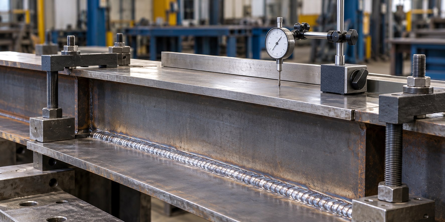
Use an instrument suited to the tolerance: a straightedge and feeler gauges may be enough for a local plate alignment, while a total station, level, dial indicator or displacement transducer may be appropriate for a girder. The engineer should set the acceptance limit. “Looks straight” is not an acceptance criterion.
Recheck fit-up before welding. The weld fit-up inspection record should show that joint preparation, root opening, alignment and tack-weld condition match the approved detail. A distorted joint should be referred for disposition before production welding begins rather than pulled into position with uncontrolled force.
Turn the sequence into field hold points
1. Confirm the plan at the start of each shift
Review the exact joint, pass sequence and measurement points with the welder, foreman and inspector. Verify the WPS revision, consumable control and preheat method. The sequence card should be clear enough that a change in personnel does not become a change in process.
2. Control tacks and restraint
Tack welds and fixtures influence shrinkage. Inspect their location, size and condition against the approved plan. Do not add a clamp, bridge tack or temporary attachment simply because a gap shifts during welding. It may solve a visible alignment issue while locking stress into the detail. If a planned restraint has to be adjusted, pause for the designated authority.
3. Follow the mapped pass order
For symmetrical details, alternating sides or working about the neutral axis can distribute heat more evenly when the approved procedure calls for it. For splices or multi-joint assemblies, partial passes may be staged across joints before any one joint is completed. The correct pattern is detail-specific: it must be based on the approved procedure, not a rule of thumb.
Record the start and stop point of each planned segment, side, pass group and any interruption. A sequence record is useful only when each planned pass group can be tied to a geometry reading and an acceptance decision. This also complements the temperature controls described in steel repair weld preheat and interpass QA/QC.
4. Measure at planned pauses
Check geometry after tacking, after initial balancing passes, after major pass groups, after fixture changes and after final cooling when required. Compare readings with the baseline and the engineer’s limits. Do not wait until the weld is complete to discover that the member has rotated beyond tolerance.
Use clear stop-work triggers
A good plan says what happens when readings are not as expected. Examples include a measured movement approaching the action limit, a loss of fit-up at an adjacent joint, unexpected restraint, a cracked tack, a failed temperature control, or evidence that the actual member condition differs from the drawings. Stop the affected work, preserve the records and notify the authority named in the repair plan.
Do not use flame heating, peening, forceful jacking, cutting or re-welding as an automatic correction. Those actions can affect material properties, residual stress, weld quality and the structural response. Any corrective method must be engineered and authorized. If cracking or suspect weld quality is found, use the approved inspection and repair process; ultrasonic weld testing is one possible method only when the specification and qualified personnel call for it.
Inspect the finished repair and its records
Final acceptance combines weld inspection, geometry and documentation. Visual inspection should address weld size, contour, discontinuities and the surrounding member condition in accordance with the project requirements. FHWA’s steel-structure inspector checklist reinforces the need to use approved drawings, verify material and welding controls, and record the inspection.
The closeout package should retain the approved sequence, WPS references, preheat/interpass records, fit-up and geometry readings, restraint changes, inspection results, nonconformance reports and written dispositions. These records let an owner understand what was actually done and create a baseline for later inspection.
Limitations for owners and project teams
Weld sequencing is not a substitute for structural analysis, a repair design, qualified welding personnel or specified nondestructive examination. Existing cracks, section loss, fatigue details, coatings, live loads and restricted access can materially change the repair approach. Where the repair affects a primary load path, the engineer of record should define the sequence and acceptance criteria before work proceeds.
Structural Rehab can help owners organize assessment findings, repair scopes and QA/QC questions for a qualified engineering team. That consultation support does not replace site-specific design, code compliance or the engineer’s authority over the work.
FAQ
Can the welder choose the sequence in the field?
Only if the approved repair documents or WPS explicitly permit that choice. For a structural repair, the sequence should be established or accepted by the responsible engineering and welding authorities before production work.
Does a straight weld bead prove the member stayed aligned?
No. Weld appearance and member geometry are separate checks. Compare measured readings at the specified control points with the approved acceptance limits.
Should clamps be removed as soon as welding is complete?
Follow the approved sequence. Removal timing can affect shrinkage and load transfer, so it should be a planned hold point with any required readings, not a convenience decision.
Sources
- AASHTO/NSBA Guidelines for Field Repairs and Retrofits of Steel Bridges
- FHWA Bridge Welding Reference Manual
- FHWA Steel Structures Inspector’s Checklist
Need a professional structural assessment?
Book a consultation with Structural Rehab to evaluate repair priorities, corrosion risks, and rehabilitation options before damage escalates.
Book Consultation