
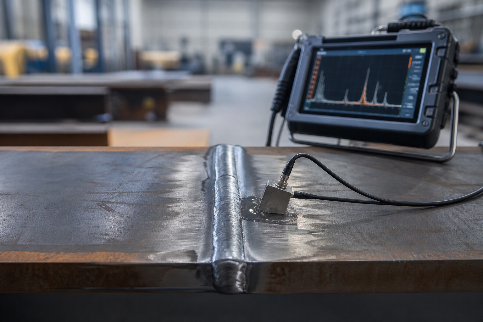
Ultrasonic weld testing can examine the internal volume of many structural-steel welds without cutting the joint open. That capability makes it valuable for fabrication quality assurance, repair verification, and selected investigations of existing structures. It does not, however, turn an instrument trace into an automatic statement about structural capacity. A reliable examination begins with the governing code, a suitable procedure, qualified personnel, accessible geometry, and a clear record of where every relevant indication was found.
This guide explains how owners, engineers, inspectors, and repair teams can plan ultrasonic testing (UT) for structural steel welds, control the field work, and use the results without overstating what the method proves.
What ultrasonic weld testing actually measures
A UT instrument sends high-frequency sound into steel through a probe and couplant. Reflections return from boundaries such as the back wall, weld geometry, or a discontinuity. The examiner evaluates travel time, probe position, beam angle, response amplitude, and scanning behavior to estimate an indication’s location and characteristics. Angle-beam techniques are commonly used for weld examination because they can direct sound through the weld volume from the adjacent base metal.
The FHWA ultrasonic flaw-detection overview identifies applications including cracks, lack of fusion, inclusions, and porosity in steel bridge welds. Detection capability depends on flaw orientation, size, surface condition, joint geometry, material properties, and the procedure used. A discontinuity is not automatically a rejectable defect: acceptance comes from the applicable contract, code edition, joint category, and engineer-approved criteria.
Flaw detection is not thickness gauging
Both applications use sound, but their questions differ. A corrosion survey seeks remaining plate thickness, often with a straight-beam thickness gauge. Weld UT seeks reflections within a joint, commonly with angled shear waves and a defined scan plan. For section-loss work, see our guide to ultrasonic thickness testing of corroded structural steel. A thickness reading beside a weld does not substitute for a coded weld examination.
Start with the engineering question and governing requirements
Before mobilization, the engineer should identify the welds, joint types, material thicknesses, loading significance, inspection stage, and reason for examination. Is the work required production QA, confirmation after a weld repair, investigation of a suspected crack, or condition assessment of an existing detail? Each purpose can require a different extent, calibration, reporting threshold, and acceptance route.
AWS D1.1/D1.1M:2025-AMD1 is the current AWS structural welding code for commonly used carbon and low-alloy steels, but a project may contractually invoke another edition or another code. The AISC welding inspection and NDE guidance emphasizes that the examination method, extent, technique, and acceptance standard must be established. Bridge work may invoke AWS D1.5, agency specifications, or project provisions rather than building requirements. Existing-structure repairs may also need the engineer to define how current inspection results are reconciled with the original design and construction basis.
Do not copy a percentage or acceptance table from an unrelated project. Record the precise governing document, edition, clause, weld category, and any engineer-approved modifications in the inspection plan.
Pre-examination hold points
Confirm personnel and procedure qualification
The written practice, examiner qualification, equipment, probes, reference blocks, calibration intervals, and reporting forms should be reviewed before testing begins. Qualification should match the method, technique, code, and responsibility assigned. Instrument ownership or general NDT experience alone is not evidence that a person is qualified for the specified structural-steel weld examination.
Map the joint and accessible scanning surfaces
Record member marks, weld identification, joint configuration, thickness, weld length, access sides, obstructions, coatings, backing, and surface condition. Verify that the scan surface permits stable probe contact and full coverage of the required examination volume. Roughness, curvature, limited approach, attachments, and inaccessible sides can create blind zones. If full coverage is impossible, the limitation belongs in the report and must be referred to the engineer rather than hidden behind a generic “tested” status.
Examine the base-metal scan path
Base-metal laminations or other reflectors can mask or distort the weld examination. The adjacent scanning area should be checked as required by the procedure, and interfering conditions should be mapped. Surface preparation should remove material that prevents coupling or probe movement without unnecessarily grinding away evidence. For repair planning around a known discontinuity, coordinate UT with the controls in our welded steel connection repair guide.
Field QA/QC during ultrasonic scanning
Calibration is a hold point, not paperwork after the scan
Calibrate with the specified reference block and probe arrangement before acceptance scanning. Confirm the range, zero or wedge delay, sensitivity, reference level, beam angle or index point, and any transfer correction required by the procedure. Recheck calibration at required intervals, after equipment changes, and at the end of the examination period. If a check is outside tolerance, quarantine the affected results and repeat the necessary work.
Use a documented scan plan
The plan should show probe types and angles, scan directions, index limits, coverage, surface, sensitivity, evaluation level, and overlap. Move the probe systematically while maintaining coupling. Mark and investigate relevant responses from more than one position where the procedure requires it. The inspection grid must preserve each indication position relative to the weld, not let the most convenient screen capture become the engineering record.
UT is technique-sensitive. AISC notes that it can miss flaws and can also produce responses that are not rejectable. Phased-array UT can improve encoded records and coverage in suitable applications, but it adds procedure, calibration, data-quality, and personnel requirements; it does not remove the need for competent interpretation. The FHWA PAUT overview describes both straight-beam and angle-beam applications and their use for weld flaws.
Control changing material and acoustic behavior
Material type, heat treatment, grain structure, thickness transitions, temperature, surface coatings, and dissimilar acoustic paths may affect sound transmission. For steel bridges, FHWA’s recent concern about acoustic dissimilarities is summarized through the NSBA technical resources. Where the material response does not match the procedure’s assumptions, stop and obtain technical direction; do not compensate informally until an indication looks acceptable.
Interpreting and documenting indications
A useful report allows another qualified person and the engineer to understand what was examined and how. At minimum, include:
- project, structure, member, joint, weld, and drawing identifiers;
- governing code, edition, procedure, acceptance criteria, and examination extent;
- examiner identity and qualification basis;
- instrument, software if applicable, probe, wedge, frequency, reference block, and calibration records;
- material, thickness, joint geometry, scan surfaces, surface condition, temperature where relevant, and access limitations;
- scan directions, sensitivity, transfer correction, and coverage;
- each reportable indication’s position, length or extent determined by the approved method, response data, and disposition;
- areas not examined or incompletely covered, with reasons;
- repair and re-examination linkage, including revision history.
Do not describe every reflector as a “crack.” UT responses can arise from weld profile, root geometry, backing, inclusions, lack of fusion, porosity, laminations, or other interfaces. Classification and acceptance must follow the procedure and governing criteria. If the indication is safety-critical or ambiguous, the engineer may request a complementary method, additional scan angles, PAUT, radiography, surface examination, or carefully controlled excavation.
Repair, re-examination, and engineering disposition
When an indication is rejectable, preserve its coordinates before grinding or gouging begins. Define repair limits, temporary support needs, welding procedure, heat input controls, access, inspection stages, and final acceptance. Surface methods may assist during excavation: compare magnetic particle testing for ferromagnetic steel and liquid penetrant testing for clean, nonporous surfaces.
After repair, re-examine the required volume using the specified method and document the relationship between the original indication, excavation, repair weld, and final result. Acceptance of the NDT result confirms compliance with the stated examination criteria; it does not by itself verify member capacity, fatigue life, residual stress, fracture toughness, or the adequacy of an unreviewed repair detail.
Owner’s ultrasonic weld testing checklist
- Define the engineering question and weld population.
- Identify the governing code, edition, clause, extent, and acceptance criteria.
- Approve the procedure and confirm examiner qualification.
- Verify joint geometry, material, thickness, access, and scan coverage.
- Hold the work for initial calibration and scan-plan review.
- Require base-metal checks and documented limitations.
- Audit indication mapping, calibration checks, and traceable records.
- Send ambiguous or rejectable results to the responsible engineer.
- Link repair instructions and re-examination to the original indication.
- Retain raw data where the technique and contract require it.
Frequently asked questions
Can ultrasonic testing prove that a structural steel weld is safe?
No. UT supplies evidence about detectable reflectors within the examined volume under stated conditions. Safety and capacity require engineering evaluation of the joint, loads, materials, detail, damage, acceptance basis, and method limitations.
Is ultrasonic testing better than radiography?
Neither method is universally better. Detectability varies with flaw orientation, thickness, geometry, access, safety constraints, and code requirements. The engineer should select the method that fits the likely discontinuities and required evidence.
Can UT find every crack or lack-of-fusion flaw?
No. Orientation, size, location, beam path, surface condition, geometry, material response, equipment, procedure, and examiner skill affect detection. Reports should state coverage and limitations.
Does a phased-array image eliminate interpretation?
No. PAUT can provide encoded data and multiple beam angles, but it still needs a qualified procedure, suitable calibration, controlled acquisition, competent analysis, and governing acceptance criteria.
Should coatings be removed before weld UT?
It depends on coating condition, thickness, coupling, procedure qualification, and required sensitivity. If a coating prevents stable scanning or changes response beyond the approved procedure, prepare the surface or obtain an engineered alternative.
Plan the examination around the decision
Structural Rehab can help owners define weld populations, inspection hold points, repair sequences, and engineering dispositions for concrete and steel rehabilitation. Book a consultation to review the structure, records, access constraints, and applicable requirements before field testing or repair begins.
Need a professional structural assessment?
Book a consultation with Structural Rehab to evaluate repair priorities, corrosion risks, and rehabilitation options before damage escalates.
Book Consultation