
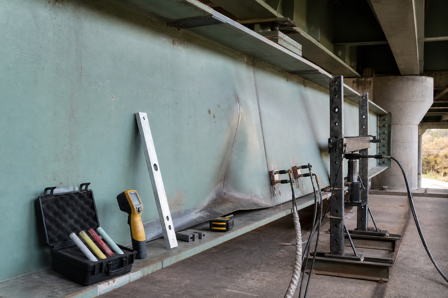
Heat straightening can restore the geometry of an impact-damaged steel bridge member without cutting it out, but it is not simply “heating the bend.” It is an engineered repair process that combines structural assessment, controlled restraint, prescribed heating patterns, temperature limits, measurements, and inspection. Used without that control, heating can worsen distortion, initiate cracking, damage coatings, or change material properties.
This guide helps bridge owners, engineers, inspectors, and contractors decide when heat straightening steel bridge repair is appropriate and define the evidence needed for acceptance. It is based primarily on the Federal Highway Administration’s 2023 Manual for Heat Straightening, Heat Curving and Cold Bending of Bridge Components, which supersedes earlier FHWA guidance.
Start with emergency control, not a torch
A vehicle strike or other overload can leave a girder carrying load through a geometry and stress state that did not exist before the event. The first decisions concern public safety: restrict traffic if necessary, protect the area below, document the as-found condition, and determine whether temporary support is required. Do not pull, jack, heat, drill, weld, or remove bracing until the responsible engineer has evaluated the load path.
Record global alignment and local damage before anything is moved. Useful records include survey coordinates, flange and web offsets, lateral sweep, member twist, local buckles, connection deformation, bearing position, cross-frame condition, photographs with scale, and the position of impact scars. Our guide to temporary shoring and load-path control explains the same governing principle: temporary work must be designed as part of the structural solution.
Determine whether the member is a candidate
Heat straightening uses localized thermal expansion followed by contraction during cooling to produce permanent movement. It is best suited to certain plastic deformations in otherwise repairable steel. It cannot be selected from appearance alone. The engineer should classify the damage, identify the steel, check member criticality, evaluate cracks and section loss, and decide whether the required movement can be achieved without unacceptable restraint or secondary damage.
Map the damage mechanism and geometry
FHWA organizes common damage into basic modes such as strong-axis bending, weak-axis bending, local buckling, and combinations of these modes. A real bridge strike may also distort diaphragms, connections, stiffeners, bearings, or adjacent girders. The repair plan should describe each mode because heating patterns and restraint arrangements depend on the deformation being corrected.
Measure both the visible peak deformation and the transition into apparently straight steel. Check whether the web is wrinkled, the flange is kinked, welds are torn, bolts have slipped, or attachments have forced a local distortion. Compare field geometry with drawings and with an undamaged companion member where appropriate. A convenient straightedge reading is not a substitute for a repeatable survey baseline.
Identify material and fracture concerns
Review mill records, plans, fabrication era, repair history, and previous fire or heating exposure. Material grade and toughness matter, especially for fracture-critical or tension components and for high-strength quenched-and-tempered steels. When records are uncertain, the engineer may require testing rather than assuming a modern weldable grade.
Impact can create cracks that are hidden by coating, rust, or geometry. Clean selected areas and use an appropriate nondestructive examination method based on the suspected flaw orientation and location. The welded steel connection repair guide discusses visual testing and surface or volumetric NDE selection. Any crack changes the repair decision; heating across an unaddressed crack is not an acceptable shortcut.
Separate distortion from metal loss
Heat straightening changes geometry; it does not restore thickness or replace torn steel. Measure corrosion or impact gouging separately and analyze the remaining section. Where capacity must be reinstated, the solution may combine straightening with plates, member replacement, connection work, or another engineered detail. See structural steel section loss repair for the measurement-to-capacity workflow.
Engineer the repair sequence
A successful heat-straightening repair is controlled plastic movement, not improvised force. The written plan should define the target geometry, heating pattern locations and orientation, permissible temperature range, heating equipment, restraint points, jack or come-along arrangement, force limits, cooling rules, measurement intervals, stop-work triggers, inspection hold points, and final tolerances.
Analyze the member in its damaged condition and through the proposed sequence. Dead load, live-load restrictions, continuity, bracing, cross-frame participation, composite deck action, and temporary restraint can all affect response. If external force is used, it should be measured or otherwise reliably controlled. Excessive jacking can introduce yielding at the wrong location or trigger instability.
Choose heating patterns that match the deformation
Common patterns include vee heats, line heats, and spot heats. Their dimensions, orientation, spacing, and sequence determine where contraction occurs. The pattern should be shown on the repair drawing or procedure and transferred to the member. Heating a broad area because it “looks bent” gives poor control and makes temperature and movement difficult to reproduce.
Plan incremental cycles. Measure after cooling, compare the result with the predicted direction and magnitude, and adjust only within the engineer-approved procedure. The safest field rhythm is heat, cool, measure, inspect, and document—not continuous heating until the member appears straight.
Control temperature and cooling
The governing specification and material-specific procedure must set maximum heating temperature and measurement method. Temperature crayons, contact instruments, infrared devices, or calibrated combinations may be used, but emissivity, surface condition, distance, and instrument range can affect readings. The crew should demonstrate how temperature will be checked before production heating begins.
Do not invent a universal temperature from a generic article. Allowable values depend on material, process, and owner requirements. The FHWA manual provides engineering guidance, while the project engineer remains responsible for selecting limits. Cooling should also follow the approved procedure; accelerated quenching can create steep gradients and unintended behavior when it is not specifically permitted.
Build QA/QC around hold points
The quality plan should make responsibilities explicit. The contractor controls execution; the engineer approves the procedure and changes; inspection verifies the specified steps and records objective evidence. Qualified personnel and demonstrated experience are especially important because field judgment is unavoidable even with a detailed plan.
Recommended pre-heating hold point
- Traffic control, access, fall protection, fire prevention, and protection of utilities are active.
- The as-found survey, damage map, photographs, and NDE results are accepted.
- Material identity and any restrictions on heating are resolved.
- Cracks, tears, severe gouges, and section loss have an engineer-approved disposition.
- The repair sequence, patterns, restraint arrangement, temperature limits, and tolerances are issued.
- Thermometers, force-measurement devices, and survey equipment have current calibration or verification.
- Coatings and combustibles are removed or protected within the controlled work area.
Record every heating cycle
The daily log should identify the member and heat location, pattern type and dimensions, heat number, starting geometry, applied restraint or force, maximum observed temperature, heating and cooling times, ambient conditions, geometry after cooling, inspector, and any anomaly. Marking a heat map on drawings makes later review much clearer than relying on photographs alone.
Stop-work triggers should include unexpected movement, cracking or audible fracture, temperature excursion, restraint slippage, equipment failure, movement in an adjacent member or connection, or results that depart materially from the predicted trend. A safe heat-straightening repair is a measured sequence with permission to stop.
Inspect after straightening
Final geometry is only one acceptance criterion. Reinspect high-strain zones, weld toes, stiffener ends, attachments, holes, and any location that showed distress during the work. Perform the specified NDE after the member has cooled and is accessible. Confirm connections, cross-frames, bearings, and deck interfaces remain serviceable. If welding is part of the repair, use an approved welding procedure and inspection plan rather than treating it as incidental work.
Repair damaged corrosion protection after surface preparation and inspection are complete. Establish coating hold points for surface cleanliness, environmental conditions, stripe coats, and dry film thickness; our steel coating QA/QC guide provides a practical closeout framework.
Acceptance and owner closeout
Define geometric tolerances before work begins, including the measurement reference and whether tolerances apply to local curvature, sweep, twist, flange tilt, or global alignment. “Looks straight” is not an acceptance standard. The engineer should also confirm structural adequacy in the repaired configuration and document any residual deformation intentionally accepted.
The closeout package should include the approved procedure and revisions, calculations, material information, pre- and post-repair surveys, heat maps and cycle logs, instrument records, NDE reports, crack or weld repair records, coating records, photographs, acceptance statement, and future inspection instructions. Flag repaired locations in the bridge file so later inspectors know what changed and where focused examination is warranted.
When replacement or another repair is better
Heat straightening may be inappropriate when fracture, severe local damage, unfavorable material, excessive strain, inaccessible geometry, repeated prior heating, instability, or uncertain load paths prevent reliable control. Replacement can also be more practical when the member has extensive section loss, multiple damaged details, or poor fatigue performance. The decision should compare safety, constructability, traffic impact, durability, inspection burden, and life-cycle value—not just initial cost.
The method is also not a substitute for fatigue-crack repair, connection redesign, or capacity strengthening. Those needs may coexist with geometric correction and must be addressed explicitly.
Frequently asked questions
Can any bent steel girder be heat straightened?
No. Suitability depends on damage mode and severity, material, fracture risk, member criticality, access, restraint, and the ability to control and verify the process. An engineer must evaluate the specific member.
Does heat straightening weaken structural steel?
Controlled heat straightening within an engineered procedure has a long history of successful use. Uncontrolled temperature, excessive force, repeated cycles, or unsuitable steel can adversely affect performance. That is why material assessment, temperature limits, cycle records, and inspection are mandatory.
Should the girder be unloaded first?
Not automatically. The required load restriction, shoring, jacking, or restraint depends on the damaged load path and repair sequence. The responsible engineer must establish the safe load state before heating.
Is visual inspection enough after the repair?
Usually not by itself. Acceptance commonly combines dimensional survey, visual inspection, specified NDE, connection and bearing checks, structural review, and complete documentation.
Can the existing paint remain during heating?
The work plan must address coating removal, fumes, fire risk, contamination, and restoration. Coatings can interfere with inspection and temperature measurement and may be damaged by heat. Follow the project safety and environmental requirements.
Get an evidence-based repair plan
Structural Rehab can help owners organize damage surveys, engineering hold points, repair specifications, inspection records, and durable closeout requirements for damaged concrete and steel structures. Book a structural rehabilitation consultation to discuss the evidence needed for your project. You can also use our practical resources to prepare questions for your engineer; they do not replace a project-specific structural assessment.
Authoritative sources
- FHWA-HIF-23-003: Manual for Heat Straightening, Heat Curving and Cold Bending of Bridge Components
- FHWA Demonstration Project on Heat-Straightening Repair of Damaged Steel Bridge Members
- National Steel Bridge Alliance: Guide for Heat-Straightening of Damaged Steel Bridge Members
- AISC Engineering Journal: What You Should Know About Heat Straightening Repair of Damaged Steel
Need a professional structural assessment?
Book a consultation with Structural Rehab to evaluate repair priorities, corrosion risks, and rehabilitation options before damage escalates.
Book Consultation