
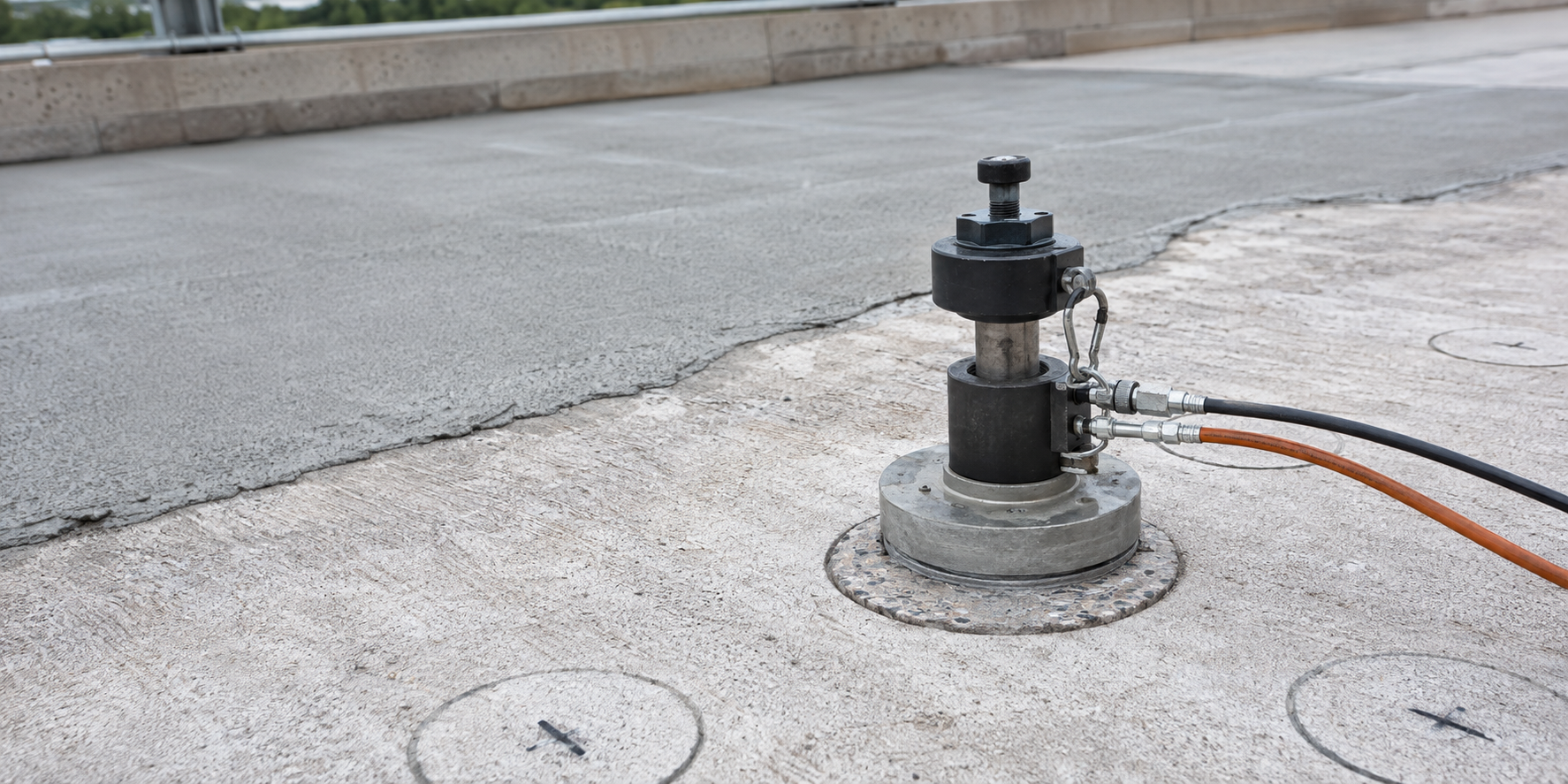
Direct-tension pull-off testing gives an owner something a visual inspection cannot: a measured indication of the weakest tensile plane in a prepared concrete surface, repair, or bonded overlay. Used well, it can help qualify surface preparation and verify completed work. Used carelessly, one number can be mistaken for proof that an entire repair is sound.
The essential rule is simple: record both the stress and the failure location. ASTM C1583/C1583M explains that a test on a repair system may measure interface bond, repair-material tensile strength, substrate tensile strength, or even the dolly adhesive—whichever fails first. The result therefore has meaning only when the fracture surface, test geometry, curing age, and project acceptance criteria are documented together.
What a pull-off test can—and cannot—tell you
A direct-tension test uses a metal loading fixture, often called a dolly, bonded to an isolated circular test area. A pull-off device applies force perpendicular to the surface until the specimen separates. The peak force divided by the measured test area gives the reported tensile stress.
Before repair placement, the method can indicate the near-surface tensile strength of the existing substrate and help identify damage left by concrete removal. After placement, it can assess a bonded repair or overlay system. FHWA describes the method as a practical field tool for checking surface preparation and the bond of repair materials or overlays to concrete.
It does not directly establish structural capacity, shear-friction resistance, durability, watertightness, or service life. A few passing points do not prove that every square metre is bonded. Conversely, a low result does not automatically prove interface failure: the old concrete may have failed cohesively below a sound bond. Pull-off data belong inside a broader repair QA/QC plan.
Define the engineering question before testing
Substrate qualification before placement
Testing a prepared substrate asks whether the remaining near-surface concrete is strong enough for the proposed bonded repair. Locations should represent the removal method, member condition, orientation, and variability of the work. If impact removal may have bruised or microcracked the surface, results can help determine whether additional removal or a less damaging preparation method is needed. Our guide to concrete surface profile before repair explains why roughness alone is not evidence of sound concrete.
Acceptance of a repair or overlay
Testing after curing asks whether the installed system achieves the specified tensile performance at the selected age. The specification should state the test method, number and distribution of tests, conditioning, age, acceptance rule, treatment of outliers, required failure-mode records, and repair of test holes. Avoid choosing a universal threshold copied from another project. The required value should reflect the design basis, substrate strength, repair system, exposure, and governing documents.
Investigating a suspected bond problem
Diagnostic testing can compare sound-appearing and suspect zones, but the sampling plan must avoid confirmation bias. Combine results with sounding, visual mapping, repair records, moisture history, and—where justified—cores or other investigations. See the related guide to concrete delamination surveys for planning area-wide screening.
Plan representative test locations
A defensible plan divides the work into meaningful lots rather than scattering convenient points. Consider different substrate conditions, repair materials, placement days, crews, preparation equipment, horizontal versus overhead work, edges, congested reinforcement, and areas exposed to unusual moisture or temperature. Random selection within each lot reduces the chance that only the best-looking locations are tested.
Before drilling, locate reinforcement, tendons, conduits, embedded sensors, and other hazards. A pull-off core is small but still destructive. Coordinate isolation depth so the cut crosses the intended interface when bond is being evaluated without striking embedded items. The rebar-locating guide covers the limits of cover meters and ground-penetrating radar.
Record the member, grid reference, repair lot, material batch, placement and test dates, surface orientation, temperature, moisture condition, nominal repair thickness, dolly diameter, core depth, device identification, calibration status, loading rate, peak load, calculated stress, and photographs before and after failure. These records make a result traceable instead of merely numeric.
Control the field procedure
- Confirm readiness. Verify the specified curing age and any moisture or temperature conditioning. Testing too early may answer a different question from final acceptance. Coordinate timing with the repair curing and protection plan.
- Prepare the surface locally. Remove contaminants and weak surface films without damaging the test zone. The dolly adhesive must bond more strongly than the plane being evaluated.
- Isolate the specimen correctly. Core perpendicular to the surface, with the specified diameter and depth. For a bonded repair, the cut normally extends through the repair and into the substrate so the interface lies within the specimen.
- Bond and align the dolly. Center the fixture, control the adhesive thickness, allow full adhesive cure, and keep adhesive out of the annular cut. Eccentric loading can distort the stress distribution.
- Apply direct tension. Seat the device so the reaction system is stable and aligned, then load at the method-required rate without shock.
- Preserve the evidence. Photograph both fracture faces, measure or describe the failed area, identify the failure plane, and retain unusual specimens for review.
Competent technicians and calibrated equipment matter. Differences in drilling, dolly alignment, adhesive cure, load rate, and failure classification can make results from nominally identical areas difficult to compare. A preconstruction trial area can align the contractor, laboratory, engineer, and owner before production testing begins.
Interpret failure mode before the number
Interface failure
A fracture concentrated between repair and substrate is the clearest indication that the test measured tensile bond at that location. Low interface results may point to contamination, insufficient or damaged preparation, surface drying, placement delay, poor consolidation, incompatible materials, or curing problems. They trigger investigation; they do not identify the cause by themselves.
Cohesive substrate failure
If fracture occurs in the existing concrete below the interface, the measured value represents the local substrate’s tensile capacity at failure. The bond and repair resisted at least that applied stress. This can be an acceptable and informative outcome, but widespread weak-substrate failures may also show that the repair is attached to a deteriorated layer that deserves further assessment.
Cohesive repair failure
Failure inside the repair material indicates that the interface and substrate exceeded the recorded stress, while the repair material governed. Review material age, mixing, placement, consolidation, thickness, and curing. Compressive-strength results cannot substitute automatically for the direct tensile evidence.
Adhesive, dolly, or mixed failure
Failure between dolly and surface usually means the setup limited the test; it may provide only a lower bound and commonly requires retesting under the project procedure. Mixed fractures need the proportions and locations documented. ASTM cautions against averaging results with different governing failure modes as though they measured the same property.
Write acceptance criteria that lead to decisions
The specification should say what happens when an individual test or lot does not comply. Options may include engineering review, additional tests around the location, sounding and mapping, limited removal to inspect the interface, correction of preparation methods, expanded repair limits, or rejection and replacement. Predetermine who selects retest locations and who has authority to accept a lot.
Do not allow repeated testing only in increasingly favorable locations until an average passes. Equally, do not reject a large repair solely because the dolly adhesive failed at one point. A sound rule links sampling, failure classification, statistics, and corrective action to the risk of the member. The pre-placement inspection hold-point guide shows how these decisions fit into the wider construction record.
Limitations owners should keep visible
- The test is local and destructive; spatial coverage is limited.
- Results are sensitive to specimen geometry, alignment, moisture, temperature, age, and loading procedure.
- The weakest plane governs, so the reported stress is not always interface bond strength.
- Reinforcement and shallow embedded items constrain safe test locations.
- Test holes must be repaired with a compatible procedure.
- Acceptance values and frequencies must be project-specific and consistent with the governing code, specification, and licensed engineer’s design.
The practical quality principle is that every result must preserve its physical meaning: a number without its fracture plane is incomplete evidence.
Owner’s pull-off testing checklist
- State whether the objective is substrate qualification, installed-repair acceptance, or diagnosis.
- Reference the correct edition of ASTM C1583/C1583M and applicable ICRI, ACI, contract, and agency requirements.
- Define lots, random selection, test frequency, age, conditioning, and orientation.
- Scan for reinforcement and embedded hazards before coring.
- Require calibrated equipment, competent technicians, perpendicular loading, and controlled loading rate.
- Report peak stress and failure mode for every test, with photographs.
- Set project-specific acceptance, retest, investigation, and repair-of-test-hole procedures.
- Keep the results with as-built repair boundaries, material batches, curing records, and nonconformance actions.
Frequently asked questions
Does a passing pull-off result prove the repair is fully bonded?
No. It verifies performance only at sampled locations under the test conditions. Sounding, inspection, material records, curing records, and representative sampling remain necessary.
What is a good pull-off strength for concrete repair?
There is no single value suitable for every repair. The engineer should specify criteria based on the substrate, repair system, design demand, exposure, test age, governing documents, and expected failure mode rather than copying a generic threshold.
Why did the concrete fail below the repair interface?
The existing concrete was the weakest tested plane at that location. This usually means the interface resisted more than the reported stress, but the condition and representativeness of the substrate still need engineering review.
Can pull-off testing replace compressive-strength testing?
No. The tests answer different questions. Pull-off testing evaluates near-surface or repair-system tensile behavior, while compressive specimens address specified compressive properties under their own procedures.
Authoritative sources
- ASTM C1583/C1583M-25: Direct Tension (Pull-off Method)
- ICRI 210.3R-2022: In-Situ Tensile Pull-Off Tests
- ICRI R³ Concrete Guides, including Direct-Tensile Pull-Off Testing
- FHWA: Tensile Bond Tester
- FHWA-HRT-16-081: Direct-Tension Testing of Bonded Grouts
- ACI RAP-7: Spall Repair of Horizontal Concrete Surfaces
Need a concrete repair QA/QC plan?
Structural Rehab can help owners define representative test lots, hold points, acceptance logic, repair records, and follow-up actions for concrete buildings, bridges, parking structures, and industrial facilities. Book a structural rehabilitation consultation to turn test data into a defensible repair decision.
Need a professional structural assessment?
Book a consultation with Structural Rehab to evaluate repair priorities, corrosion risks, and rehabilitation options before damage escalates.
Book Consultation