
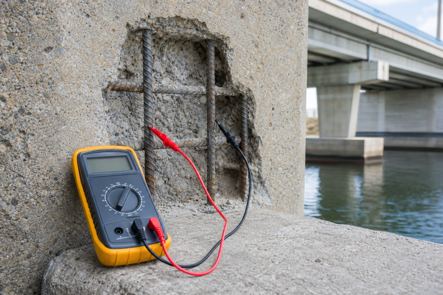
Reinforcement electrical continuity testing is a small field task with a large influence on cathodic protection performance. A cathodic protection (CP) zone can only distribute protective current to steel that is electrically connected to the system return. If bars, mats, embedded plates, or repaired areas are isolated, a rectifier may appear to operate normally while part of the intended steel receives little or no protection.
The purpose of the survey is not to prove that a CP design is adequate. It is to define the electrical network that the designer will protect, identify discontinuities that need bonding, and produce test records that can be repeated during installation and commissioning. This guide focuses on reinforced concrete. Prestressed members require specialist review because excessive polarization and unintended current paths can create additional risks.
Why continuity matters before cathodic protection
In an impressed-current system, the anode is connected to the positive side of a controlled DC source and the reinforcing steel to the negative side. In a galvanic system, the electrochemical driving voltage comes from the selected anode material. In either case, a complete electrical path is essential. The ISO 12696:2022 scope emphasizes performance criteria and monitoring for steel in concrete CP systems; continuity is part of the physical basis for demonstrating that the intended steel can respond as one protected network.
A discontinuity can occur between top and bottom reinforcement mats, across movement joints, at precast connections, around previous repairs, or where epoxy-coated reinforcement limits metal-to-metal contact. It can also be introduced when corroded tie wire is lost during breakout. Conversely, an unintended metallic connection can join separate CP zones or short an anode to reinforcement. The survey must therefore look for both missing connections and unwanted connections.
Start with a test plan, not random meter readings
Define the intended electrical zones
Mark the proposed CP zones, construction joints, movement joints, repair boundaries, reinforcement layers, embedded steel items, drains, bearings, utilities, and accessible steel connections on drawings. State which items are meant to be continuous and which must remain isolated. Coordinate this with the cathodic protection repair strategy, because continuity acceptance cannot be separated from the zoning and monitoring design.
Use existing drawings only as a starting hypothesis. Field reinforcement may differ, lap splices do not always guarantee low-resistance contact, and past repairs may have severed or replaced bars. Combine the continuity plan with rebar locating and safe access planning before drilling or exposing steel.
Select representative and critical test pairs
Test pairs should challenge the network rather than merely confirm two nearby bars. Include points across the longest practical distance in each zone, between reinforcement mats, across repair boundaries, between adjacent structural components that should be connected, and between zones that should be isolated. Add tests at embedded steel, anchorages, and services where an unintended current path would matter.
Assign every test point a durable identifier. Record its location, steel type, access method, intended relationship, meter, lead configuration, surface condition, and result. Photographs should show the wider location and the actual contact point without relying on a meter display as the only record.
Prepare equipment and contact points
Use an appropriate calibrated or function-checked low-resistance meter, insulated leads, sharp probes or secure clamps, and a separate means of checking voltage difference. Ordinary handheld meters can be useful, but lead resistance and unstable contact can be large relative to the low values of interest. Measure the resistance of the connected leads by firmly shorting the probe ends, then either zero it using the instrument function or record and subtract it in accordance with the approved procedure.
Continuity readings require metallic contact. Remove rust scale, coating, laitance, or contamination only at the approved test point and only to the extent necessary. Do not indiscriminately expose reinforcement. Confirm bar location and cover, control drilling depth, protect prestressing steel, and repair every access point with compatible material. The same care described for cleaning and assessing exposed reinforcement applies to temporary continuity taps.
A practical DC continuity test sequence
- Make the area safe. Confirm permits, isolation requirements, traffic controls, access, moisture hazards, and the status of any existing CP or electrical system.
- Identify the pair. Verify both test-point IDs and whether the design expects continuity or isolation.
- Check the instrument. Inspect leads, confirm battery and range, and document shorted-lead resistance.
- Measure open-circuit voltage. Before resistance testing, measure the voltage difference between the two steel points. Existing corrosion cells, stray current, or a depolarizing CP system can distort resistance readings.
- Measure resistance in both polarities. Record the first reading, reverse the leads, allow the display to stabilize, and record the second. Do not write only “pass.”
- Repeat doubtful results. Clean and remake contacts, confirm the same physical points, and repeat. If results remain unexpected, expand the test matrix and use a second method under the corrosion specialist’s procedure.
- Restore the structure. Protect or remove temporary leads as specified and close access points with an approved repair detail.
FHWA’s long-term CP effectiveness study describes DC, AC, and half-cell-based continuity techniques and documents the limitations of each. Its field experience is an important warning: no single resistance number should override unstable voltage, contradictory measurements, or the physical configuration of the steel network.
How to interpret readings safely
For direct connections to exposed reinforcement, a project may use a low-resistance criterion such as 1 ohm after considering lead resistance. FHWA’s current half-cell field guidance uses 1 ohm or less, including lead resistance, when checking continuity between installed reinforcement taps. That value is useful context, not a universal specification for every geometry, wire run, instrument, or installed monitoring circuit.
The acceptance rule must be written by the qualified CP designer before testing. It should define the contact arrangement, whether lead resistance is included, allowable voltage difference, stabilization time, repeatability, treatment of readings in opposite directions, and the response to an ambiguous result. Long cable runs and connections through monitoring wiring cannot be judged as though probes were touching two adjacent bare bars.
Active corrosion currents, stray DC, system depolarization, parallel paths, wet concrete, capacitance across a physical gap, and instrument input characteristics can all affect results. DC testing is commonly preferred, but unexpected readings may justify AC resistance or a potential-comparison technique. Those methods have their own failure modes: an AC signal can bridge a discontinuity through capacitance, while a potential comparison depends on stable potentials. Interpret the methods together rather than choosing the most convenient result.
Bonding, isolation, and retesting
Where required continuity is absent, the designer should specify a durable bond sized and detailed for the service environment. Common solutions include welded or mechanically secured connections and insulated copper bonding conductors, but the connection method must suit reinforcement type, fatigue exposure, welding restrictions, concrete breakout, and CP current demand. Do not weld reinforcement unless its weldability and the structural consequences are established.
Where separate zones are unintentionally connected, trace the path before cutting anything. Bearings, pipes, drainage components, anchors, handrails, or common reinforcement can create the link. Verify isolation after correction and confirm that the action has not compromised structural load paths, grounding, lightning protection, or other safety systems.
Retest after breakout and repair, after installation of bonds and monitoring points, before anode concealment, and during commissioning. Continuity is a hold point, not a one-time survey. Pair it with documented checks for anode-to-steel shorts, reference-electrode connections, zone wiring, polarity, and monitoring response.
QA/QC records owners should require
- Marked drawings showing every test point, CP zone, bond, intended isolation, and access repair.
- Instrument identification, range, calibration or function-check status, and measured lead resistance.
- Open-circuit voltage plus forward and reverse resistance readings for each pair.
- Contact preparation, weather, concrete condition, existing-system status, and stabilization notes.
- Photographs and a nonconformance record for every ambiguous or failed result.
- Corrective-action details and signed retest results.
- A final continuity matrix cross-referenced to commissioning zones and permanent monitoring leads.
A useful hold point comes before the anode system hides the reinforcement network: the engineer reviews the full continuity matrix, not a sample of “pass” marks. If the matrix does not demonstrate the intended network and isolation boundaries, installation should pause until the discrepancy is explained.
Limitations and specialist decisions
Continuity testing does not measure corrosion rate, remaining steel area, bond, structural capacity, CP current distribution, or compliance with protection criteria. Use half-cell potential mapping and linear polarization resistance testing only for their defined purposes and limitations. Neither substitutes for continuity verification.
Prestressed or post-tensioned concrete, conductive fibers, epoxy-coated reinforcement, electrical grounding systems, and operating CP installations need project-specific procedures. The CP designer must also assess the risk of overprotection, hydrogen effects, and interaction with other metallic systems. ISO 12696 applies to specific monitored CP systems and explicitly does not turn every embedded galvanic patch anode into a fully monitored CP installation.
Frequently asked questions
Does a low resistance reading prove the bars are physically tied together?
No. It indicates an electrical path between the selected points under the test conditions. Parallel steel, embedded items, moisture-related paths, wiring, or capacitance can complicate interpretation. Confirm the network with drawings, test geometry, repeat readings, and additional methods when results conflict.
Is 1 ohm always the pass criterion?
No. It is a commonly cited value for direct reinforcement contacts and appears in FHWA field guidance, but the approved project procedure must address lead resistance, distance, connection type, voltage difference, and installed wiring. Apply the designer’s criterion, not an isolated number copied from another project.
When should continuity be tested?
Test during investigation, after concrete removal exposes the actual reinforcement, after bonds or repairs are installed, before anodes are concealed, and during commissioning. Repeat tests when later work can sever or inadvertently join the network.
Can a standard multimeter be used?
It may be suitable for some field checks if its resolution, lead compensation, contact quality, and safety rating meet the approved procedure. Very low resistance work may require four-wire or specialist equipment. Always record lead resistance and voltage difference.
What should happen after a failed reading?
First verify identity, contact quality, lead condition, meter range, and interfering voltage. Repeat in both polarities and test additional points to locate the boundary. The CP designer should then specify bonding or isolation correction and require a documented retest.
Plan the electrical network before installation
Structural Rehab helps owners and engineers define investigation hold points, continuity matrices, concrete repair interfaces, and CP QA/QC records for concrete and steel rehabilitation. Book a structural rehabilitation consultation to review a proposed scope, or use our concrete and steel structures repair ebook as a practical planning reference. Final design, electrical safety, and site acceptance remain the responsibility of qualified project professionals.
Need a professional structural assessment?
Book a consultation with Structural Rehab to evaluate repair priorities, corrosion risks, and rehabilitation options before damage escalates.
Book Consultation