A dimensional survey for a structural-steel repair establishes the geometry that the approved repair must preserve or deliberately change. It is more than a quick tape-measure check after work is complete. A steel repair dimensional survey QA/QC record gives the engineer, contractor and owner a shared baseline for fit-up, alignment, elevations and final acceptance.
This article is a QA/QC framework for an engineered repair of a bridge, building or industrial steel structure. It does not authorize field changes to member geometry, connection details, welding, bolts, temporary works or load paths. The engineer of record and applicable project documents define the measurements, tolerances and repair disposition.
Why a baseline survey matters
Existing steel is rarely a perfect replica of the drawings. It can have fabrication tolerances, previous repairs, camber, settlement, service deflection, impact damage, section loss or movement caused by repair-stage supports. If the team measures only after a repair, it cannot distinguish pre-existing geometry from movement introduced by the work.
FHWA’s steel-structure inspector checklist calls for approved drawings and field inspection records, including checks of dimensions and girder profile against plan requirements. The AASHTO/NSBA field-repair guideline likewise treats inspection and documented repair procedures as integral to reliable steel bridge rehabilitation. Those principles translate to other structural-steel work, but the project-specific criteria remain controlling.
Define the survey question before choosing an instrument
Start by writing down the decision that each reading will support. A local splice repair may need plate position, bolt-hole centerlines, flange offset and root-gap checks. A damaged girder may need elevation, sweep, web plumbness, bearing position and adjacent-member clearance. A repair involving temporary support may require readings before unloading, at staged load transfer and after release.
Do not collect measurements merely because an instrument is available. The approved repair package should identify:
- the member and repair limits, applicable drawing revision and required control geometry;
- the datum, benchmark or stable reference points and how they are protected;
- the location, direction and units for each reading;
- the instrument, calibration status, operator and required accuracy;
- the acceptance and action limits, including who can interpret a deviation;
- the planned survey stages and any stop-work triggers; and
- the responsible person for resolving a nonconformance.
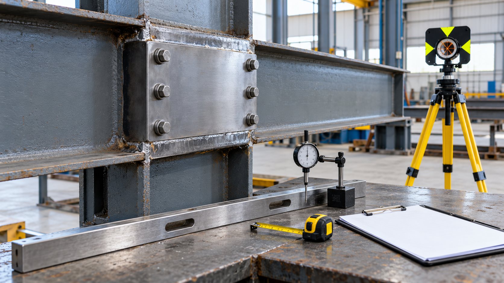
A tape, straightedge, level, total station, laser, dial indicator or displacement transducer can all be appropriate in the right setting. Select the tool after the tolerance and decision are defined. A precise reading from an unsuitable datum does not establish structural alignment.
Build a traceable baseline
Use stable, meaningful control points
Choose points that are visible, repeatable and outside the expected work disturbance where practical. For example, an engineer may identify locations on a flange, web, bearing line, connection plate or adjacent stable member. Avoid relying on a corroded edge, an unverified temporary attachment or a paint mark likely to be removed during surface preparation.
Record enough information for another qualified person to repeat the observation: point identifier, description, sketch or photo reference, instrument setup, date, time and measured value. A survey diagram should distinguish design targets from observed baseline readings. Do not overwrite a baseline with a later reading.
Separate geometry from material condition
A dimensional survey can reveal a visible offset, rotation or clearance concern, but it does not establish member capacity, section loss, crack severity or weld soundness. Pair it with the appropriate assessment work. For example, suspected cracking requires the approved inspection approach; ultrasonic weld testing may be specified for some weld conditions, while a survey addresses geometry rather than internal weld quality.
Use hold points through the repair sequence
A valuable survey record captures change, not just a final number. Set measurement stages around irreversible or load-changing operations. The exact sequence must be engineered, but a common framework is:
- Pre-work baseline: confirm the existing condition before removal, heating, jacking, unloading or fit-up.
- After preparation: check that removal limits, remaining steel and repair interfaces match the approved detail before a plate, bolt group or weld obscures them.
- Fit-up release: verify position, gap, alignment and temporary restraint before production welding or final bolt installation. See the separate weld fit-up inspection workflow for joint-specific controls.
- Intermediate work stage: take readings at approved pauses, especially after staged jacking, major weld groups or support changes.
- Final acceptance: compare cooled, stabilized geometry with the approved criteria and baseline; record the engineering disposition of every material difference.
Do not make temporary support removal a convenience step. The release of repair-stage supports can alter load paths and deflections; it needs an engineer-defined sequence, monitoring and acceptance process. Temporary support release QA/QC explains why the handover must be controlled rather than improvised.
Control fit-up without forcing the steel
When a repair plate, member or connection does not fit the design geometry, pause and document the condition. Pulling a component into position with clamps, heat, force or unreviewed slotting may hide the visible discrepancy while changing restraint, residual stress or connection behavior. The appropriate response is an engineer’s written disposition based on the actual condition.
FHWA’s Bridge Welding Reference Manual notes that conditions involving a change to bridge geometry require engineer involvement and that repair proposals should provide enough information for a thorough evaluation. The practical lesson is simple: a survey finding becomes useful only when it reaches the person authorized to decide whether the design, repair procedure or acceptance limit must change.
Make records usable at closeout
A closeout package should let a future inspector reconstruct the decision process without guessing. Include the approved drawing and repair revision, baseline survey, instrument and calibration information, point-location sketch, stage readings, photos where allowed, fit-up records, inspection reports, nonconformance reports and final written dispositions.
FHWA’s bridge inspection QC/QA framework emphasizes documented roles, validation, error resolution and records. Even on a private building or industrial asset, assigning roles and retaining the evidence makes it much easier to confirm that a measured exception was identified, reviewed and closed rather than simply missed.
Limitations and owner guidance
Survey readings are not a substitute for structural analysis, a repair design, load rating, qualified welding inspection or code compliance. Temperature, live load, access, vibration, instrument setup and reference stability can influence measurements. For a primary load path, a fatigue-sensitive detail, a bridge under traffic, or a repair with jacking or welding, the engineer of record should set the observation plan and acceptance criteria before work begins.
Structural Rehab can help owners organize condition findings, questions for the engineer and the QA/QC records needed for a repair scope. That support does not replace project-specific design, inspection authority or the responsible engineer’s decisions.
FAQ
Is a final measurement enough for steel repair acceptance?
Usually not. A final measurement cannot show whether a discrepancy existed before the repair or developed during it. A baseline and planned intermediate readings provide the context needed for engineering acceptance.
Can a contractor set the tolerance in the field?
No. Tolerances and acceptance decisions should come from the approved repair documents or an authorized engineer’s written disposition. The field team records the observed condition and preserves it for review.
What if the repair plate does not align with the existing steel?
Stop the affected work, verify the survey and fit-up observations, and request an engineered disposition. Do not assume that extra force, heat, reaming or altered welding is an acceptable correction.
Sources
- AASHTO/NSBA Guidelines for Field Repairs and Retrofits of Steel Bridges
- FHWA Bridge Welding Reference Manual
Need a professional structural assessment?
Book a consultation with Structural Rehab to evaluate repair priorities, corrosion risks, and rehabilitation options before damage escalates.
Book Consultation