
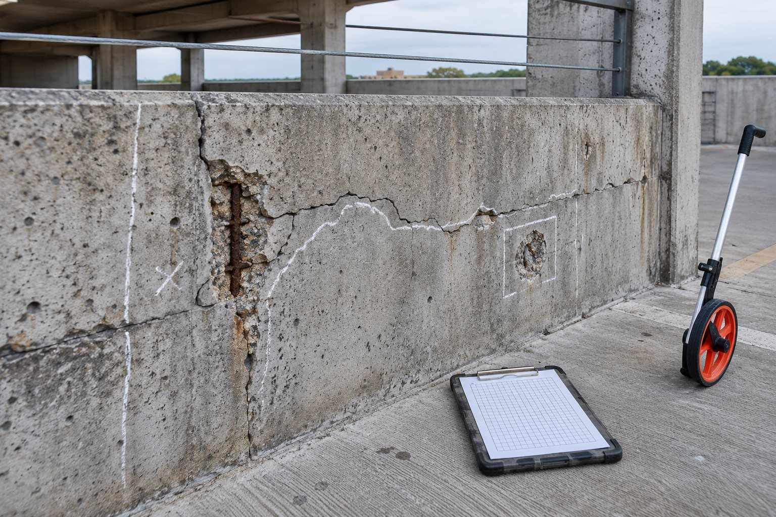
A concrete repair scope is only as reliable as the condition information behind it. A marked spall on a drawing can be useful, but it does not explain whether the distress is shallow or deep, isolated or widespread, active or historic, or connected to a durability problem that will continue after patching. A disciplined concrete repair condition survey mapping process turns site observations into repair limits, quantities, inspection priorities, and a record that the owner can use when conditions change.
The survey is not a substitute for an engineering assessment. It is the organized field evidence that supports one. Before a contractor prices work or a team chooses a repair method, the engineer of record needs to know where the observed distress is, what was observed, how it was located, and what uncertainty remains. That sequence helps prevent a quantity takeoff from becoming an untested repair design.
Start with the question the survey must answer
Write a survey plan before walking the structure. A useful plan identifies the members or zones to be inspected, the visible distress types to record, the location reference system, access limits, the intended use of the data, and the escalation path for safety concerns. The plan should distinguish an observation from a diagnosis. “Spall, approximately 0.3 square metre, sounding limit not established” is an observation; “repair with a 50 mm patch” is a design decision that requires appropriate evaluation.
ACI CODE-562-25 describes assessment and repair of existing concrete structures as an engineered process. Its assessment framework is a useful reason to record environment, geometry, material condition, reinforcement information where available, and signs of distress before settling on a rehabilitation strategy. For an overview of the assessment decision sequence, see our guide to evaluating existing concrete structures before repair.
Build a map that another person can use
Use stable references: grid lines, column numbers, beam marks, deck stationing, elevations, room coordinates, or a controlled photo plan. Avoid relying only on “near the north wall.” Each surveyed area should have a unique identifier that connects the field sketch, photo, observation, test result, and eventual repair record. If the structure has different construction eras, exposure conditions, or repair histories, divide it into zones rather than blending unlike conditions into one total.
For every mapped item, record the member or zone, distress type, approximate dimensions, apparent severity, date, observer, access condition, and whether the boundary is visible, inferred, or awaiting further investigation. A simple legend prevents later confusion: use separate marks for cracking, delamination indications, spalls, exposed reinforcement, leakage, prior repairs, staining, and test locations. Do not draw a crisp repair perimeter when the actual limit has not been confirmed.
A repair quantity is a planning number until the field boundary and repair depth are confirmed. This distinction matters for budget control. A surface-area total can support preliminary planning, but depth, reinforcement condition, hidden delamination, and substrate soundness can materially change concrete removal and replacement quantities.
Collect observations in a repeatable sequence
1. Review available records and exposure
Start with drawings, earlier repair records, maintenance reports, drainage details, leak history, loading changes, and prior investigation data. Then note exposure: marine spray, chlorides, wet-dry cycling, leaking joints, industrial chemicals, fire exposure, or repeated impact may alter both the likely cause and the investigation needed. This review makes the field walk more efficient and prevents the team from treating every visible defect as the same mechanism.
2. Perform a visual survey and document uncertainty
Photograph overall context first, then close views with a scale and location reference. Record cracks by location, orientation, apparent width range, and whether they show displacement, moisture, staining, or movement evidence. For spalls and disintegration, note whether reinforcement is exposed, whether corrosion products are visible, and whether the area may extend behind a finish or below the surface. Safe access and site-specific safety controls come first; inaccessible conditions should be marked as unobserved rather than guessed.
3. Use screening tools for their intended purpose
Sounding, chain drag, hammer sounding, infrared thermography, cover-meter surveys, half-cell potential measurements, impact-echo, cores, and laboratory testing can answer different questions. None should be reported as proof of a condition it cannot establish. For example, a sounding response can help identify a suspected delamination boundary, but it does not establish corrosion rate or structural capacity. Our concrete delamination survey guide explains how sounding and selective NDE can support repair-limit mapping.
Match the method to the decision. If the issue is whether deterioration is limited to a shallow repair zone, investigation may need to establish depth and sound substrate. If the issue is corrosion exposure, chloride content, carbonation depth, electrical continuity, cover, and moisture may be relevant. If capacity is in question, an engineer may need material testing and structural analysis rather than a broader visual survey.
4. Reconcile the map before pricing or construction
Review the survey with the owner, engineer, and contractor before the quantity schedule is fixed. Group repairs by type and uncertainty: confirmed localized patches, areas requiring additional investigation, contingent quantities, and locations that could change from partial-depth to full-depth work. FHWA guidance for concrete pavement repairs similarly emphasizes examining the extent of deterioration and marking repair boundaries from field-survey information, with a follow-up review close to construction because conditions can change.
Turn survey data into a usable repair scope
A repair scope should state what is known and how deviations will be handled. It can identify preliminary quantities, but it should also describe the criteria for expanding a repair area, the authority for changing repair type, required inspection hold points, and documentation needed for payment or acceptance. This is especially important when hidden deterioration is likely. The field team needs permission to stop and obtain a decision—not an incentive to force every condition into the original patch outline.
For patch repair, define when removal stops: sound concrete, stable edges, acceptable reinforcement clearance, and the project-specific depth or geometry required by the repair detail. Then document the final limits after removal. The related concrete repair saw-cut boundary workflow covers stable perimeter details, while post-repair sounding acceptance addresses a later QA/QC question after placement.
QA/QC records owners should request
Keep the record traceable but practical. A good package includes the survey plan and legend; marked drawings or digital map; photo log; member and grid references; test and sample locations; access limitations; observed distress quantities; assumptions; unresolved areas; and the date of the last verification. Link each changed repair limit to an inspection record and the approved disposition. Daily placement records should then link back to the repair-area identifier; our concrete repair daily-log guide shows the value of tying field observations to installation records.
Common mistakes to avoid
- Counting visible damage as the final repair quantity: visible area is not necessarily the removal boundary or repair depth.
- Mixing different distress mechanisms: one map symbol for every defect hides information needed for repair selection.
- Using unlocated photographs: a photo without a member reference cannot reliably support scope, change control, or future inspection.
- Ignoring conditions that changed after the original survey: recheck near construction, especially in exposed or actively deteriorating areas.
- Turning screening results into a structural conclusion: use each test method within its limits and involve the engineer when capacity, stability, or repair design is at stake.
Limitations and engineering judgment
Condition mapping helps define where to investigate and repair; it does not certify structural adequacy, determine a root cause by itself, or establish a repair design. Hidden deterioration, embedded reinforcement, prestressing, active corrosion, water ingress, unsafe access, and changed loading can require a more detailed assessment. The engineer of record should set the investigation scope, repair criteria, and acceptance requirements for the specific structure.
FAQ
How accurate is a concrete repair quantity survey?
It depends on access, method, and whether the depth and hidden extent of deterioration have been verified. Use preliminary quantities for planning, then establish field controls for measurement and approved changes as repair boundaries are opened.
Should repairs be mapped again immediately before work starts?
Yes, when deterioration could have progressed, access has improved, or the construction schedule is distant from the original survey. The project quality plan should state who confirms changed conditions and how the record is updated.
Can a contractor decide the final repair limit in the field?
The contract documents should define the contractor’s inspection and notification duties, but changes to repair type, structural details, or significant limits should follow the engineer’s approved process. Field observations do not replace design authority.
Plan repair quantities with evidence, not assumptions
A clear condition map makes uncertainty visible before it becomes a claim, delay, or unsuitable repair. Structural Rehab can help owners develop condition-survey scopes, repair documentation, and QA/QC hold points for existing concrete structures. This article is general information and not a substitute for a project-specific assessment, repair design, or safety plan.
Sources
- ACI CODE-562-25: Assessment, Repair, and Rehabilitation of Existing Concrete Structures
- USACE EM 1110-2-2002: Evaluation and Repair of Concrete Structures
- FHWA: Full-Depth Concrete Repair Construction Procedure
- FHWA: Concrete Pavement Preservation Guide
Need a professional structural assessment?
Book a consultation with Structural Rehab to evaluate repair priorities, corrosion risks, and rehabilitation options before damage escalates.
Book Consultation