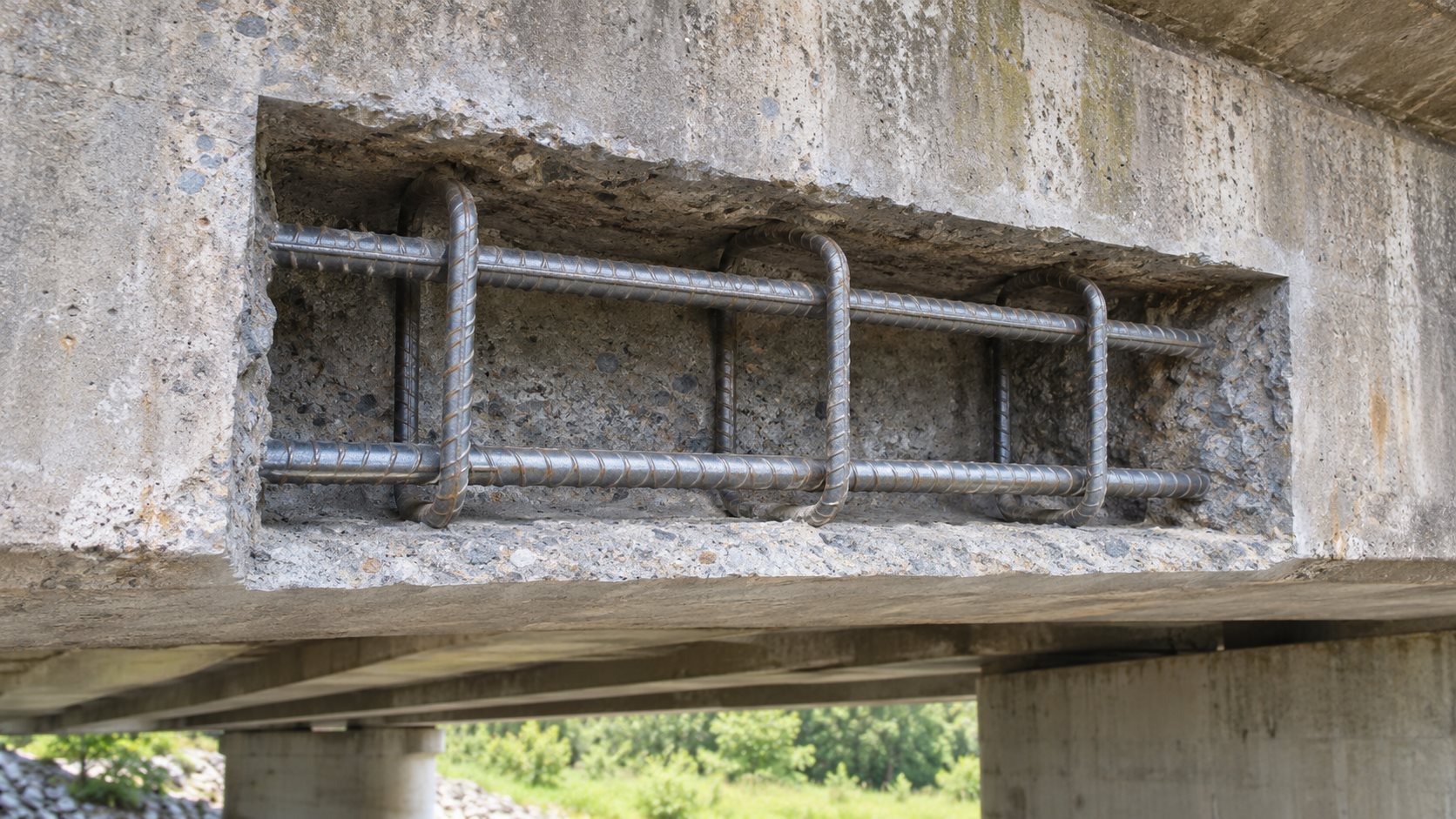
When a concrete repair exposes mild reinforcing steel, the visible bar is not a cue to simply coat it and place mortar. The repair must provide enough access to inspect, clean, and surround the reinforcement with the specified material while preserving the member’s engineered load path. That makes reinforcement clearance a practical QA/QC hold point, especially in deep spalls, beam repairs, pier repairs, and bridge-deck work.
This guide explains how owners, engineers, contractors, and inspectors can organize field observations and release records around exposed mild reinforcement. It applies to conventional reinforced concrete, not prestressed strand or post-tensioned tendons. It does not replace the engineer of record, contract documents, material instructions, or a repair design.
Why clearance around reinforcement matters
Concrete repair material must reach and consolidate around exposed steel without leaving voids, trapped debris, or a thin edge that cannot perform as intended. Limited access can also hide corrosion on the back side of a bar, prevent cleaning, and make it difficult to verify that the prepared cavity has a continuous bondable surface. A repair may look complete from the face while still containing an unobserved defect behind the reinforcement.
TxDOT’s major-spall procedure illustrates the engineering issue: when substantial perimeter exposure or significant corrosion is present, concrete may need to be removed around the full bar; it also calls for clearance sufficient for repair material to flow around the steel. The exact dimensions and disposition for a project remain design and specification decisions. A field team should not convert a general guide into an unapproved demolition limit.
Clearance is only one part of a repair system. The team still needs a defined repair boundary, sound substrate, suitable material, reinforcement assessment, placement method, curing plan, and acceptance criteria. Use it alongside a disciplined pre-placement inspection for concrete repairs rather than treating it as a stand-alone pass/fail number.
Set the hold point before concrete removal begins
Identify what the drawings and repair procedure require
Before chipping starts, confirm the repair ID, member function, limits shown on the drawings, reinforcement information available, repair depth, material system, and planned placement method. Name who can authorize a larger removal area, who can assess reinforcement section loss, and who releases the repair for placement. Where corrosion, cracking, or a load-path concern extends beyond the planned boundary, stop and obtain direction instead of expanding the work by assumption.
Distinguish mild reinforcing steel from prestressing. Exposed prestressing strand needs a separate, engineer-led response because striking, cutting, or loosening it can have serious consequences. Our guidance on exposed prestressing strand in concrete repair covers that different risk. This article is limited to mild reinforcement in a designed reinforced-concrete repair.
Choose observations that can be documented
A useful hold point asks questions a competent inspector can record: Is the bar exposed on the required sides? Can the preparation and cleaning be seen behind it? Is there enough room for the specified repair material and placement method? Is loose concrete, dust, rust scale, or standing water still present? Has the repair boundary reached the approved sound material? Record observations against the repair plan instead of using a generic photograph as the acceptance basis.
Confirm how clearance will be checked. Depending on geometry, that may be direct measurement, a gauge, a template, camera documentation, or an engineer’s visual review. Note the reference points and the locations checked. A single measurement at the widest portion of a cavity does not establish access around the whole exposed bar.
Control removal without damaging sound concrete or steel
Removal work should progress to the approved limits with tools and energy appropriate to the repair documents. The crew should avoid striking reinforcement and avoid leaving fractured or delaminated concrete at the boundary. The purpose is not to make a cavity look symmetrical; it is to expose a durable, bondable repair surface and the required access around steel while retaining sound parent concrete.
As reinforcement becomes exposed, inspect the back side and adjacent concrete. Corrosion staining at the face may indicate that deterioration continues beyond the first visible patch. If the bar is still bonded to unsound concrete, if corrosion extends to an approved boundary, or if the bar’s condition differs from the repair assumptions, document the condition and obtain a disposition. Do not conceal a condition change by applying repair mortar over an unexamined area.
For deep repairs, the placement approach matters. A hand-applied mortar, form-and-pour repair, flowable grout, or pneumatically applied system can have different access and consolidation needs. The approved product data and method statement govern. Material selection and availability should already be controlled through the same receiving records described in our concrete repair material storage and shelf-life guide.
Inspect, clean, and assess the exposed reinforcement
Make the full condition visible
Before cleaning, record bar identification where practical, exposed length, sides exposed, apparent corrosion, nearby cracking, and any bar deformation or damage. The repair drawings may require an engineer to assess section loss, splices, anchorage, or supplemental reinforcement. A contractor or inspector should report those observations; they should not decide that an altered bar is structurally adequate without the authority defined by the project.
Clean the bar and adjacent concrete using the approved method so contaminants and corrosion byproducts do not remain between the repair material and the prepared surfaces. Cleaning should not damage the bar, alter required coatings without direction, or spread debris onto a prepared substrate. When a protective coating, corrosion-control measure, or galvanic anode is specified, verify the approved product, preparation, placement, and inspection points. Do not add one merely because reinforcement is exposed.
Verify access for the actual repair material
Now assess whether the cavity geometry lets the specified material reach behind and around the steel. Look for bridge points where a trowel, hose, nozzle, aggregate, or grout flow cannot reasonably pass. Check cover and repair depth against the design, not against a preferred visual profile. FHWA’s underwater repair reference manual similarly emphasizes that clearance behind steel and specified cover affect bond and durability; its discussion is useful context, but project-specific requirements control above all.
If the geometry cannot be released, do not force material through a narrow gap, add water, or use an unapproved smaller aggregate or product. Escalate for an engineered change to the repair limits, material, formwork, or placement method. That decision should be captured before placement, when correction is still straightforward.
Use a practical release record
A short record makes the hold point repeatable across a repair program. Tie it to the repair ID, drawings, batch documents, and inspection log. Include the following:
- Location and limits: member, face, repair ID, orientation, planned versus actual prepared area.
- Reinforcement observation: bar type where known, sides exposed, cleaning status, apparent corrosion, and any condition needing engineering review.
- Clearance check: method, reference locations, observed access behind and around steel, and any restriction.
- Repair-system readiness: approved material, placement method, substrate condition, formwork or access arrangement, and curing protection.
- Decision: release, re-clean, extend preparation under approval, revise method, or hold for engineering disposition.
- Authority and time: inspector, contractor representative, engineer when required, date, and linked photographs.
Connect the release record to concrete repair daily logs. That creates a trace from observed steel condition through preparation, material placement, curing, and later acceptance work. It is more dependable than a recollection after the repair is covered.
Common errors to avoid
Do not assume every exposed bar requires replacement, and do not assume every cleaned bar is acceptable. Replacement, splicing, anchorage, cover, and corrosion-control decisions belong in the repair design. Do not chip blindly around reinforcement to obtain a preferred clearance; removal can change the member condition and may expose other steel or services. Do not treat a photo of the front face as proof that the back side was prepared. Finally, do not proceed when the specified material cannot be placed and consolidated as intended.
Limitations
This article provides a QA/QC framework, not repair dimensions, bar-replacement rules, development lengths, cover requirements, allowable section loss, or material instructions. Those values depend on member type, loads, exposure, reinforcement details, repair geometry, and project documents. Repairs involving prestressing, post-tensioning, seismic detailing, containment over traffic, or a suspected capacity loss require an engineered repair plan and responsible-professional review.
FAQ
How much clearance is needed behind exposed reinforcing steel?
Use the repair drawings, specifications, and material instructions. Clearance must suit the repair material and placement method; a generic number should not replace project requirements or engineering judgment.
Can a crew place repair mortar if only the front of the bar is accessible?
Not unless the approved repair system and design specifically allow that condition. If material cannot be placed and consolidated around the required surfaces, hold the work and seek a documented disposition.
Does exposed reinforcement automatically mean the bar must be replaced?
No. The responsible engineer should evaluate the observed condition against the repair design. Cleaning, supplemental reinforcement, replacement, corrosion control, or another action may be required depending on the project.
Need a clearer repair QA/QC framework? Structural Rehab can help owners turn repair documents into practical hold points, inspection questions, and decision records. Our guidance supports conversations with the responsible design professional; it does not replace site-specific engineering.
Sources
- TxDOT Concrete Repair Manual: Major Spall Repair and Concrete Replacement
- FHWA: Underwater Bridge Repair, Rehabilitation, and Countermeasures Reference Manual
- FHWA: Full-Depth Concrete Repair Design Considerations
Need a professional structural assessment?
Book a consultation with Structural Rehab to evaluate repair priorities, corrosion risks, and rehabilitation options before damage escalates.
Book Consultation