
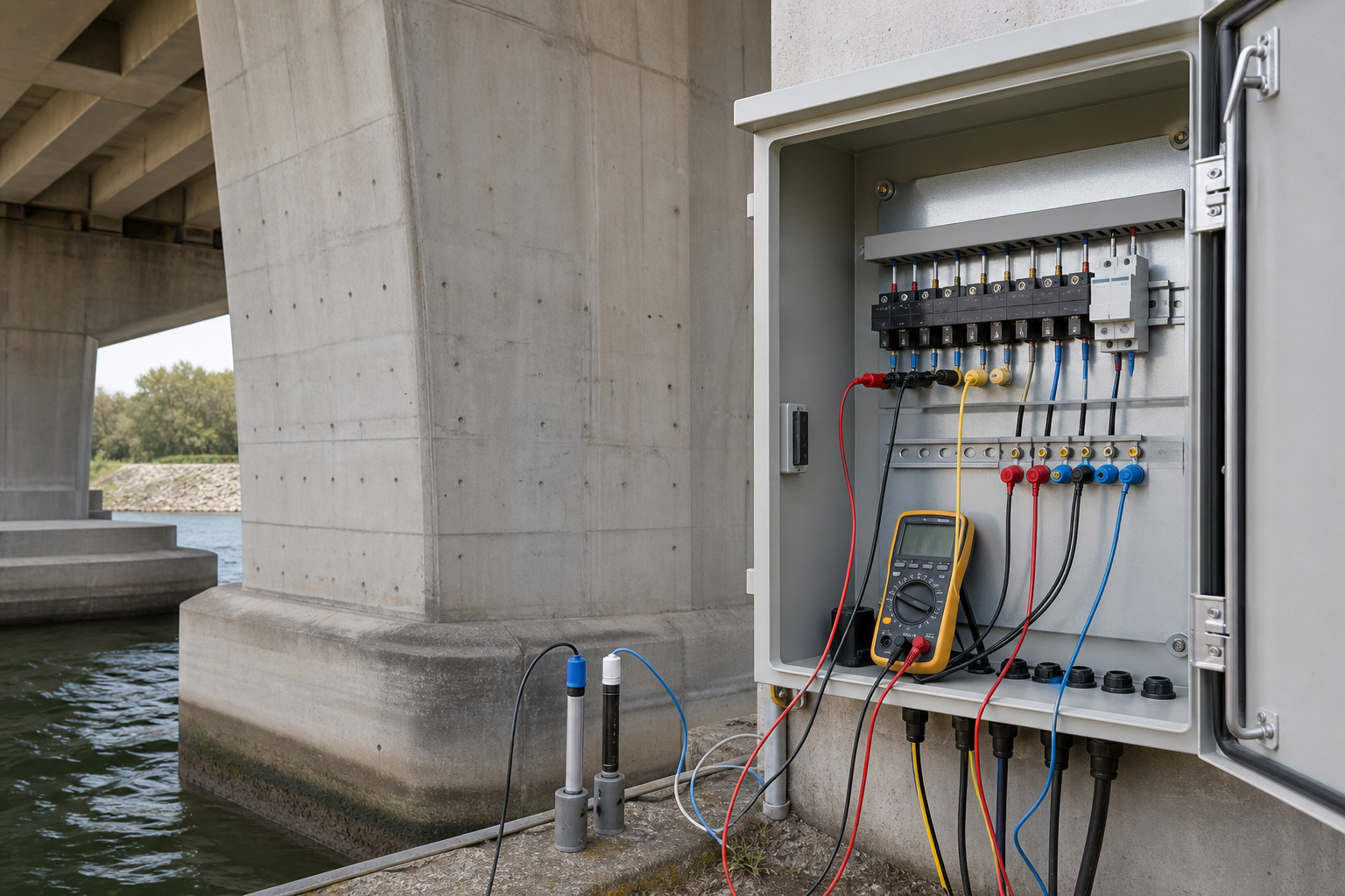
Commissioning is the point where a cathodic protection installation becomes a demonstrably controlled corrosion-protection system. For reinforced concrete, energizing an anode or accepting a completed galvanic installation is not enough. The owner needs baseline measurements, functioning monitoring points, verified electrical isolation, stable records, and evidence that the specified protection criteria are met across every intended zone.
A commissioned system is one that can prove its performance again after the contractor leaves. This guide explains the owner, designer, specialist, and inspector hold points that make that possible.
Why commissioning deserves its own work package
Cathodic protection changes the electrochemical condition of reinforcement by delivering protective current. Impressed-current systems use a controllable power source; galvanic systems use the potential difference between the anode material and the steel. Both require a design suited to the structure, exposure, reinforcement network, concrete condition, and required service life.
ISO 12696:2022 specifies performance requirements for cathodic protection of steel in concrete and explicitly requires sufficient performance-monitoring systems for all parts intended to be protected. That principle should shape procurement: monitoring is part of the protection system, not an optional accessory.
Commissioning also establishes the baseline against which seasonal checks, alarms, output adjustments, sensor drift, cable failures, and future repairs will be assessed. Missing baseline data turns later troubleshooting into guesswork.
Pre-commissioning prerequisites
Approve the design basis and zones
The documents should identify anode zones, protected steel, power or galvanic connections, monitoring locations, reference electrodes, test points, design current, control philosophy, protection criteria, access arrangements, and environmental assumptions. Zone boundaries must make engineering sense and be traceable on drawings and at the cabinet.
Verify reinforcement continuity and isolation
The target reinforcement must have the continuity required by the design, while the anode circuit must remain isolated from the steel except through the intended electrolyte path. Shorts can defeat control, distort readings, concentrate current, or damage components. Follow the companion guide to reinforcement electrical continuity before cathodic protection and keep the signed results in the commissioning dossier.
Complete repairs and acceptance inspections
Concrete repairs, anode installation, overlays, conductive coatings, jackets, cables, junction boxes, seals, and penetrations should pass their specified inspections before energization. Record deviations and repairs. Hidden components need photographs, coordinates, and as-built markups before they are covered.
Reference electrodes and monitoring points
Reference electrodes provide the stable comparison needed to measure reinforcement potential. Their material and configuration must suit the concrete environment and project specification. The Bureau of Reclamation field-installation guide describes permanent reference-electrode types and emphasizes environment-dependent selection, cable integrity, design life, and performance characteristics.
Place monitoring points where they can demonstrate performance in representative and demanding parts of each zone. Consider exposure, reinforcement density, concrete resistivity, moisture, anode geometry, repair boundaries, current distribution, and access. A convenient cabinet location cannot substitute for sensors that actually represent the protected structure.
Before acceptance, confirm sensor identity, polarity, cable route, terminal number, insulation, shielding where specified, stability, response to system switching, and agreement with a suitable portable reference check when the procedure allows. A plausible voltage is not enough evidence that a buried reference electrode is healthy.
A practical commissioning sequence
- Freeze the as-built configuration. Confirm zone maps, terminal schedules, component IDs, cable labels, anode quantities, reference-electrode locations, and protected-steel connections.
- Inspect safely before power. Verify enclosure rating, earthing, surge protection, isolation, fusing, ventilation, cable glands, seals, warning labels, and electrical safety under the applicable rules.
- Repeat critical electrical checks. Confirm reinforcement continuity, anode-to-steel isolation, zone separation, cable continuity, polarity, and circuit resistance using the approved procedure.
- Record native conditions. Obtain stable pre-energization potentials and relevant environmental observations before applied current changes the system.
- Energize gradually. For impressed-current systems, increase output under specialist control while observing voltage, current, current density, reference response, and any unexpected heating or instability. Follow the designer’s ramping and stabilization periods.
- Measure every zone. Record operating output, individual circuit current where available, structure-to-electrolyte potentials, instant-off or decay measurements where specified, and portable-reference comparisons.
- Demonstrate criteria. Apply only the protection criteria named in the governing standard and project specification. Do not invent a universal voltage, current-density, or decay threshold.
- Challenge the monitoring system. Confirm data channels, timestamps, scaling, alarms, communication, power-loss behavior, local display, remote access, and data export.
- Resolve anomalies. Investigate nonresponsive sensors, reversed polarity, excessive circuit resistance, shorts, uneven distribution, unstable readings, or zones that cannot meet criteria. Re-test after repair.
- Approve settings and baseline. Lock or document final controls, establish alarm limits, define the next inspection interval, and obtain the responsible specialist’s acceptance.
How to interpret measurements safely
Potential readings depend on the reference-electrode type, electrical connection, concrete moisture, temperature, current flow, voltage drop, and timing after switching. The test report must state the reference scale and measurement method. Mixing readings from different electrode types without correct conversion makes trends unreliable.
Protection criteria are not interchangeable with ordinary corrosion-survey thresholds. The site’s guide to half-cell potential testing explains that potentials do not directly measure corrosion rate or structural capacity. Under cathodic protection, applied current further changes the interpretation, so a qualified corrosion specialist should assess the complete response.
Concrete resistivity influences current distribution and seasonal behavior. Review relevant baseline data from concrete resistivity testing, but do not treat a resistivity value as a protection criterion. Chloride profiles, cover, moisture, cracks, and repair boundaries also help explain why nominally similar zones behave differently.
Reference-electrode failure modes
Permanent sensors can drift, dry out, lose contact, suffer cable damage, develop high circuit resistance, or become electrically noisy. FHWA’s long-term cathodic-protection evaluation notes that high reference-cell circuit resistance combined with no response to changes in current can indicate malfunction and can make readings prone to noise.
Commissioning should therefore include redundancy and diagnostic routes. Provide accessible test stations, portable-reference measurement locations, spare channels where justified, and an agreed method to distinguish a failed sensor from a real change in protection. Never tune the whole system around one questionable reading.
QA/QC records the owner should receive
- approved design basis, protection criteria, calculations, zone drawings, specifications, and accepted deviations;
- as-built locations for anodes, reinforcement bonds, reference electrodes, probes, cables, junctions, cabinets, and test points;
- material certificates, batch records, equipment calibration, sensor data, and installation inspection forms;
- continuity, isolation, polarity, resistance, and short-circuit test results;
- pre-energization, energization, stabilization, instant-off, decay, output, and environmental readings as applicable;
- raw data as well as calculated summaries, with reference scales, units, timestamps, operators, instruments, and calibration status;
- photographs before concealment and at final cabinet termination;
- alarm tests, remote-monitoring checks, backup behavior, user accounts, and data-retention settings;
- final operating settings, acceptance statement, exceptions, corrective actions, and re-test evidence;
- operation manual, safe isolation procedure, inspection schedule, spare-parts list, and named responsibilities.
Long-term monitoring after handover
Commissioning is the first point on a trend line. The maintenance plan should define routine visual inspections, electrical measurements, sensor validation, cabinet maintenance, calibration, data review, alarm response, and specialist review. Frequency should reflect system type, exposure severity, consequence of failure, power reliability, access, and early performance.
The FHWA reinforced-concrete bridge case study illustrates cathodic-protection arrangements that include monitoring stations and reference electrodes. Remote monitoring can improve visibility, but communications alone do not validate a sensor or prove uniform protection. Periodic field verification remains necessary.
Coordinate the monitoring plan with the broader post-repair structural monitoring program. Cathodic-protection data should be reviewed alongside cracking, delamination, leakage, repairs, exposure changes, and structural inspections.
Limitations and specialist responsibilities
Cathodic protection is a specialist engineered system. Incorrect design or adjustment can leave areas under-protected, create excessive polarization, mask sensor faults, or introduce risks to prestressing and other embedded metals. Work on energized equipment also requires electrical safety controls. The responsible engineer and corrosion specialist must define criteria, interpret anomalies, approve settings, and assess any interaction with prestressed steel, conductive fibers, coatings, or adjacent systems.
Commissioning does not repair existing section loss, restore bond, replace unsound concrete, or establish structural capacity. Those matters belong to the structural assessment and repair design. Start with the broader guide to cathodic protection for reinforced concrete repair when deciding whether CP is appropriate at all.
Frequently asked questions
Can a system be accepted when the power supply turns on?
No. Acceptance requires verified circuits, functioning monitoring, stable baseline records, safe operation, and evidence that specified protection criteria are satisfied in all intended zones.
Is one reference electrode enough?
Not automatically. Quantity and location depend on zone size, geometry, exposure, current distribution, variability, redundancy, and the monitoring strategy. The design must demonstrate adequate coverage.
Can half-cell corrosion thresholds be used as CP acceptance criteria?
No. Cathodic-protection performance criteria and measurement procedures must come from the governing standard and project specification. Applied current changes how potentials are interpreted.
What if a reference electrode does not respond when current changes?
Treat it as an anomaly. Check connections, resistance, noise, reference condition, instrument setup, and comparison measurements before changing system output.
Does remote monitoring eliminate site inspections?
No. It supports trending and alarms, but physical condition, calibration, portable-reference checks, cabinet integrity, and sensor validation still require planned field work.
Make commissioning a contractual hold point
Specify the evidence, responsible parties, acceptance criteria, stabilization periods, re-test rules, deliverables, and handover training before installation begins. Structural Rehab can help owners review a cathodic-protection commissioning plan and connect its results to the wider repair strategy. Book a structural rehabilitation consultation to review the proposed hold points and owner records.
Need a professional structural assessment?
Book a consultation with Structural Rehab to evaluate repair priorities, corrosion risks, and rehabilitation options before damage escalates.
Book Consultation