
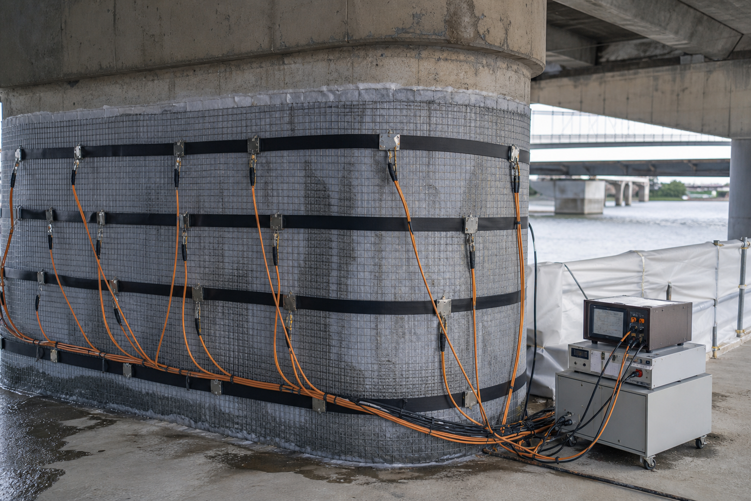
Chloride-contaminated concrete can look serviceable while corrosion is developing at the reinforcement. Conventional patching removes visibly unsound material, but it may leave a large volume of sound yet chloride-bearing concrete in place. Electrochemical chloride extraction (ECE) is a temporary specialist treatment intended to move chloride ions away from embedded steel while increasing alkalinity near the reinforcement. It can be useful in selected reinforced-concrete structures, but it is not a universal substitute for concrete removal, structural repair, or permanent cathodic protection.
This guide explains how owners and engineers can decide whether ECE deserves detailed design, what must be established before energizing the system, how treatment should be controlled, and what evidence belongs in the final record. The central principle is simple: the treatment must be designed around the actual reinforcement, concrete, exposure, and deterioration mechanism—not around a generic electrical recipe.
What electrochemical chloride extraction does
ECE uses embedded reinforcement as the cathode and a temporary external anode placed over the concrete surface. A wetted electrolyte layer provides electrical contact. Direct current drives negatively charged chloride ions toward the external anode and produces hydroxyl ions at the reinforcement. After treatment, the temporary anode, electrolyte, wiring, and containment are removed.
That makes ECE fundamentally different from permanent cathodic protection for reinforced concrete, which remains installed and monitored to control corrosion. ECE is also different from galvanic anodes used around patch repairs. It is a time-limited intervention, and its benefit depends on the amount and distribution of chloride removed, the change achieved around the steel, and the structure’s future exposure.
When ECE may be a reasonable candidate
ECE is most credible where a substantial quantity of concrete remains sound but contains enough chloride to sustain reinforcement corrosion. Avoiding wholesale removal of structurally sound concrete can reduce demolition, noise, waste, and disruption. The technique may be considered for bridge piers, decks, marine elements, parking structures, or other conventionally reinforced concrete exposed to deicing salts or seawater.
A candidate assessment should establish all of the following:
- chloride-induced corrosion is a principal deterioration mechanism;
- the reinforcement layout and electrical continuity can be mapped and verified;
- delaminated, spalled, or otherwise unsound concrete can be repaired before treatment;
- the surface is accessible enough for reasonably uniform anode and electrolyte contact;
- the structure can tolerate the proposed electrical treatment after a specialist reviews materials and detailing;
- the owner can control renewed chloride ingress after extraction.
Start with a condition survey rather than a treatment specification. Combine visual mapping with depth-specific chloride testing, cover measurement, delamination mapping, corrosion-potential data where appropriate, and selective exposure of reinforcement. Chloride samples should represent zones, depths, exposure faces, repairs, and suspected outliers—not only convenient locations.
Cases that demand caution or another strategy
ECE does not replace an engineering assessment of capacity. Significant steel section loss, bond deterioration, widespread cracking, displacement, or load-path concerns require structural evaluation and direct repair. Loose concrete must not be retained merely because ECE can move ions through adjacent sound material.
Prestressing steel, post-tensioning systems, high-strength steel, alkali-silica reaction susceptibility, electrically isolated reinforcement, embedded dissimilar metals, sensitive fixtures, and complex geometry require project-specific review. FHWA research identifies possible adverse mechanisms associated with high electrical treatment, including hydrogen effects and changes in concrete chemistry. These issues should be treated as design constraints, not as field adjustments left to the operator.
ECE is also a weak choice if the owner cannot prevent rapid chloride re-entry. A treated marine splash zone or leaking deck may soon be contaminated again unless joints, drainage, cracks, membranes, sealers, or other exposure controls are addressed. See the broader decision framework in concrete surface protection after repair.
Pre-treatment investigation and trial area
Map reinforcement and circuits
Locate reinforcement, verify cover, identify mats and discontinuities, and document connections to rails, bearings, conduits, anchors, or other metal. The embedded steel must form the intended cathode without unintentionally energizing unrelated components. Use the approach described in reinforcement electrical continuity testing, adapted by the ECE specialist to the temporary system.
Establish a baseline
Record chloride profiles at defined depths, concrete condition, resistivity or moisture indicators where relevant, corrosion observations, repairs, reinforcement continuity, surface area, and environmental conditions. Select control locations outside the treated zone when they will improve interpretation. The baseline must be detailed enough to compare like-for-like samples after treatment.
Use a representative trial
A trial area can reveal poor electrolyte retention, current crowding, high resistance, leakage, difficult edges, or unacceptable surface effects before the full installation proceeds. It should include representative cover, reinforcement density, orientation, repairs, and exposure—not the easiest square of concrete available. Agree in advance how trial results will change zoning, equipment, monitoring, or acceptance.
Design and installation controls
The design should divide the work into controllable electrical zones. Each zone needs an identified cathode connection, external anode arrangement, electrolyte and containment system, power supply limits, monitoring points, polarity checks, shutdown criteria, and traceable area calculation. Geometry matters: reinforcement congestion, thick cover, surface coatings, dry regions, and irregular edges can make current distribution uneven.
Before installing the temporary system, complete necessary concrete repairs and prepare the surface for continuous electrolyte contact. Remove materials that prevent wetting unless the specialist has demonstrated compatibility. Protect adjacent finishes, drainage systems, vegetation, traffic, and the public from electrolyte and electrical equipment. Temporary wiring must be mechanically protected, clearly routed, and secured against accidental disconnection.
Polarity verification is a formal hold point. The reinforcement is connected as the cathode and the external mesh as the anode. An incorrect connection can defeat the intended ion movement and create damage. Record connection identification and independent verification before energizing each zone.
Monitoring during treatment
ECE should be operated by qualified specialists under an engineered method statement. Do not copy voltage, current density, charge, or duration values from a case history. FHWA studies show that current efficiency changes with concrete properties, surface resistance, chloride distribution, geometry, and treatment time. Project limits must come from the design, validated trial, applicable requirements, and equipment capability.
A daily or continuously logged treatment record should include:
- zone identification, active surface area, date, and operating time;
- voltage, current, and calculated current density or delivered charge;
- electrolyte condition, level, pH where specified, leakage, and replenishment;
- temperatures, weather, interruptions, alarms, and shutdowns;
- connection condition and evidence of reasonably distributed current;
- surface observations such as drying, deposits, staining, cracking, or softening;
- corrective actions and authorization to restart.
Current alone is not proof of chloride removal. A zone can draw current while treatment remains uneven. Conversely, falling current may reflect increasing surface resistance rather than completion. Review electrical trends together with physical observations and the agreed verification sampling.
Health, environmental, and asset protection
ECE combines electricity, wet containment, alkaline electrolyte, elevated access, and potentially occupied infrastructure. The project safety plan should cover isolation, protected power supplies, lockout, trip hazards, weather, confined or public areas, chemical handling, spill control, and emergency shutdown. Only competent personnel should adjust electrical settings or connections.
Anodic reactions and electrolyte chemistry require monitoring and ventilation appropriate to the installation. Collect and dispose of spent electrolyte, felt, deposits, wash water, and temporary materials according to their characterized contents and local rules. Do not allow treatment liquid to enter drains or the environment without an approved plan.
How to verify completion
Completion should never be defined only as “the planned number of days elapsed.” The specification should combine operating evidence with post-treatment investigation. Typical evidence includes delivered charge by zone, stable and acceptable operating records, chloride profiles at predetermined locations and depths, observations at control locations, and confirmation that the concrete and embedded components have not suffered unacceptable effects.
Chloride results need careful interpretation. Compare the same sampling depths and analytical basis used at baseline. Recognize spatial variability and the possibility of chloride redistribution. A single favorable core cannot represent an entire pier or deck. Predetermine how many verification locations are required, how they are selected, what constitutes an outlier, and what happens when a zone misses the agreed objective.
Post-treatment corrosion measurements may support the assessment, but no single reading proves long-term success. For example, half-cell potential surveys indicate corrosion probability patterns, not corrosion rate, steel loss, or capacity. Interpret trends through a corrosion specialist and allow for moisture and chemical changes caused by treatment.
Handover and long-term protection
After acceptance, remove temporary materials, clean the surface, repair sampling holes and connection points, and inspect for treatment-related defects. Install the specified protection against renewed chloride entry only after confirming compatibility and moisture conditions.
The owner should receive drawings of treatment zones and connections, baseline and final chloride profiles, continuity data, trial results, equipment calibration, daily electrical logs, electrolyte records, deviations, photographs, repair records, waste documentation, acceptance decisions, and a monitoring plan. Future inspections should track cracking, spalling, corrosion indicators, drainage, joints, and protective-system condition.
Owner’s decision checklist
- Confirm the deterioration mechanism and structural adequacy.
- Map chloride by depth and location, not by one average value.
- Exclude or specially assess prestressing, sensitive steel, ASR risk, and unintended metallic paths.
- Repair unsound concrete and verify reinforcement continuity.
- Require a representative trial and project-specific operating limits.
- Define electrical, chemical, safety, environmental, and shutdown controls.
- Agree on completion evidence before treatment starts.
- Protect the treated concrete from renewed chloride ingress.
- Retain traceable records and schedule follow-up monitoring.
Frequently asked questions
Does ECE repair corroded reinforcement?
No. It can reduce chloride contamination and improve the chemical environment near reinforcement, but it does not replace lost steel area, restore bond automatically, or rebuild spalled concrete. Those defects require engineered repair.
Is ECE the same as cathodic protection?
No. ECE uses a temporary anode and higher-intensity, time-limited treatment intended to move chloride. Cathodic protection is a long-term corrosion-control system that remains installed, commissioned, and monitored.
Can treatment duration be specified in advance?
A planned range is possible, but actual performance depends on concrete, chloride distribution, cover, reinforcement, moisture, surface condition, and electrical response. Completion needs evidence, not the calendar alone.
Will chloride extraction prevent future corrosion permanently?
Not by itself. Residual chlorides, continuing exposure, cracks, leaking joints, and loss of surface protection can allow corrosion risk to return. A durable strategy combines treatment with exposure control and monitoring.
Can ECE be used on prestressed concrete?
Prestressing steel and high-strength steel raise special hydrogen and structural concerns. Do not assume suitability. A specialist must evaluate the system, materials, risks, and applicable requirements before any treatment proposal proceeds.
Authoritative sources
- FHWA-RD-02-107: Electrochemical Chloride Extraction—Influence of Concrete Surface on Treatment
- FHWA-HRT-10-069: Long-Term Effects of Electrochemical Chloride Extraction
- FHWA-RD-98-088: Corrosion Protection—Concrete Bridges
- ACI 546R concrete repair guidance: protective systems and electrochemical techniques
Need an independent repair strategy for a chloride-contaminated bridge or building? Book a Structural Rehab consultation. You can also explore Structural Rehab’s practical ebook resources for planning assessment and rehabilitation work.
Need a professional structural assessment?
Book a consultation with Structural Rehab to evaluate repair priorities, corrosion risks, and rehabilitation options before damage escalates.
Book Consultation