
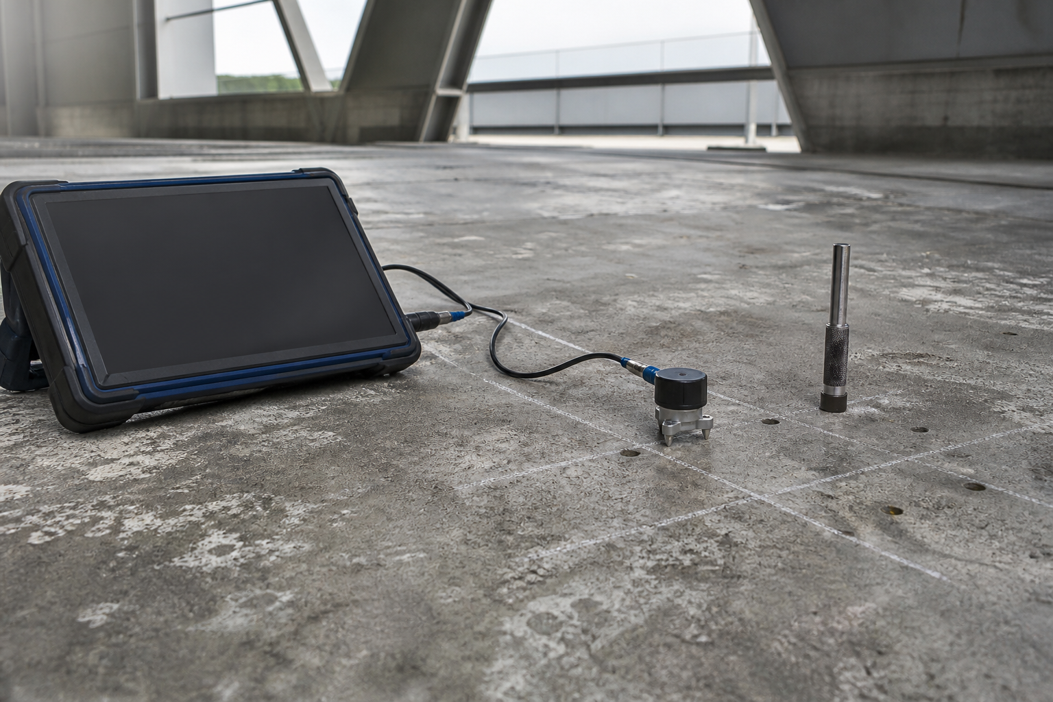
Impact-echo testing gives an engineer a practical way to investigate concrete thickness and internal reflectors from one accessible surface. It can support decisions about slabs, walls, bridge decks, pavements, and other plate-like members without immediately committing to a large coring program. The method is powerful, but it is not a push-button defect detector: survey geometry, wave speed, member shape, surface condition, and interpretation all matter.
This guide explains how owners, engineers, and inspectors can scope impact-echo concrete testing, control field quality, and use the findings responsibly in a repair investigation. It does not replace project-specific engineering judgment, structural analysis, or confirmatory openings where safety or major expenditure depends on the answer.
What impact-echo testing measures
A short mechanical impact introduces stress waves into the concrete. A receiver near the impact point records surface motion as waves reflect from the opposite face or from an internal interface. Frequency-domain analysis identifies dominant responses that may relate to member thickness or a reflector within the member.
ASTM C1383-15(2022) standardizes procedures for measuring P-wave speed and the thickness of concrete plates. The standard describes a P-wave-speed procedure and an impact-echo thickness procedure; unless otherwise specified, both are performed at each thickness location. ASTM also notes important boundaries, including limitations for plate structures with overlays and the assumption of reasonably uniform wave speed through the depth.
Impact-echo can also support internal-defect investigation. The American Concrete Institute distinguishes it from through-transmission pulse velocity: impact and response occur at the same accessible surface, and reflected energy can be used to measure thickness or locate internal defects. FHWA describes applications involving voids, cracks, and delaminations, while emphasizing planned data collection and interpretation.
When the method is a good fit
Impact-echo is most useful when the investigation has a defined question. Appropriate objectives may include:
- checking the thickness of a slab, pavement, wall, or deck where only one face is accessible;
- screening a regular grid for anomalous responses that may indicate delamination, voiding, honeycombing, or an unexpected interface;
- refining locations for cores, openings, or other confirmatory tests;
- comparing suspect and apparently sound zones within the same member; and
- documenting condition before a concrete repair or strengthening design is finalized.
The method complements—not replaces—visual inspection, drawings review, sounding, selective destructive verification, and structural evaluation. If corrosion is the suspected cause of delamination, combine the acoustic survey with exposure history and electrochemical evidence such as half-cell potential mapping. If reinforcement layout is uncertain, perform rebar locating with cover meters or GPR before choosing core or anchor locations.
Define the engineering question before mobilization
A vague instruction to “scan the concrete” invites inconsistent data and overinterpretation. The written test plan should identify the member, accessible surface, expected geometry, anticipated thickness range, known overlays or repairs, probable reinforcement, environmental constraints, and the decision the results must support.
Establish reference information
Collect available drawings, previous repair records, construction joints, core logs, and member dimensions. Mark known patches, cracks, drains, embedded items, edges, and changes in support conditions on the survey plan. These features can change the measured response or explain an apparent anomaly.
Choose a grid that matches the objective
A broad reconnaissance grid may identify zones for denser testing, but it can miss defects smaller than the spacing. A tight grid produces better spatial definition at greater field and interpretation cost. FHWA’s Long-Term Bridge Performance impact-echo protocol calls for a defined coordinate system, documented test locations, photographs, and disciplined data storage. The engineer should specify grid spacing based on the minimum feature size that matters to the decision—not on a default setting alone.
Plan validation locations
Include points of known thickness or sound condition, plus a limited number of strategically selected cores or openings where permitted. Coring should answer a specific uncertainty and avoid reinforcement or prestressing. The resulting observations help calibrate interpretations and distinguish a true reflector from geometry, material variation, or poor coupling.
Field workflow and QA/QC
1. Inspect and prepare the surface
Record cracks, scaling, roughness, standing water, membranes, coatings, and patches. Remove loose debris that prevents stable receiver contact. ASTM warns that high surface moisture can affect the P-wave-speed procedure, and its thickness method does not simply extend to every overlaid system. Do not hide such conditions in the report.
2. Confirm equipment settings and impact source
The impact must provide useful energy in the frequency range relevant to the expected thickness or defect depth. FHWA notes that impactor size affects the generated frequency range. Record the receiver type, impactor, sampling settings, software version, calibration checks, and acceptance rules. A test file without this metadata is difficult to audit later.
3. Measure or justify P-wave speed
Thickness calculations depend on wave speed. Do not import a generic velocity from another structure without engineering justification. Measure it as required by the applicable procedure, or document why a project-specific alternative is valid. Moisture, aggregate, cracking, and material variation can change wave behavior.
4. Use repeat readings and field review
At each control point, repeat impacts until the response is stable enough for the stated objective. Review waveforms and spectra in the field, not only after demobilization. Re-test erratic points, note poor receiver contact, and flag data affected by nearby mechanical impacts. ASTM specifically cautions that mechanical noise from jackhammers, hammer sounding, or sweepers can interfere even though ordinary traffic vibration is not necessarily disqualifying.
5. Map results without overstating certainty
Present measured thicknesses, dominant frequencies, confidence flags, invalid points, and anomaly zones on a plan tied to site coordinates. Preserve raw records. A successful impact-echo survey narrows uncertainty; it does not turn every spectral peak into a proven void.
Interpretation: thickness mode versus an internal reflector
For a relatively uniform plate, reflections between the test surface and opposite boundary can produce a thickness-related resonance. An internal air-filled separation can produce a different response associated with the shallower reflector. Real structures complicate this idealization: edges, beams, variable thickness, repairs, ducts, reinforcement congestion, rough interfaces, and nonparallel boundaries can all affect the spectrum.
Interpret patterns across adjacent points rather than relying on one isolated reading. Compare suspect zones with reference zones of similar geometry. Cross-check anomalies against drawings, visible cracking, sounding, and other nondestructive methods. The FHWA impact-echo technology overview illustrates the physical principle and emphasizes careful grid preparation, impactor selection, and data acquisition.
Where repair quantities or structural capacity depend on the result, verify representative anomalies. A targeted concrete core and petrographic program may confirm depth, material condition, or an interface. For suspected poor consolidation, coordinate results with the assessment framework in our honeycombed concrete repair guide.
Important limitations
- It is not a direct strength test. Impact-echo responses should not be converted into compressive strength without a separately validated relationship and appropriate method.
- Plate assumptions matter. Complex shapes, nonparallel surfaces, thickened zones, ribs, and nearby boundaries may produce responses that do not follow the simple plate model.
- Overlays can invalidate a standard thickness approach. ASTM C1383 states that its method is not applicable to plate structures with overlays such as asphalt or portland-cement-concrete bridge-deck overlays.
- Small or poorly reflecting defects may be missed. Detectability depends on defect size, depth, orientation, acoustic contrast, grid spacing, and usable frequency content.
- Interpretation requires experience. Automated classifications can help manage datasets, but an engineer must consider geometry and corroborating evidence.
- Prestressed members require special care. Testing and any validation openings must be planned so tendons are not damaged.
Turning survey findings into a repair decision
Classify findings by consequence and confidence. A thickness discrepancy may require drawing correction, local analysis, or strengthening review. A probable shallow delamination may justify sounding and selective removal. A deeper anomaly near a critical anchorage, tendon, or support may demand immediate engineering assessment and controlled verification.
Do not use a color map as a repair drawing without defining thresholds and verification. The repair documents should identify removal boundaries, temporary-support needs, reinforcement protection, inspection hold points, and how field discoveries will be handled. Before placing repair material, use a formal pre-placement inspection hold point so the substrate and reinforcement conditions match the design assumptions.
Owner’s impact-echo deliverables checklist
- survey objective and decision criteria;
- member geometry, accessible faces, overlays, repairs, and known embedded items;
- grid plan and permanent coordinate reference;
- equipment, impactor, acquisition settings, calibration, and wave-speed procedure;
- field photographs, raw waveforms, spectra, invalid readings, and repeatability notes;
- mapped results with confidence categories;
- comparison with visual, sounding, GPR, core, or other evidence;
- limitations and unresolved uncertainties; and
- engineering recommendations for verification, repair, monitoring, or analysis.
Frequently asked questions
Can impact-echo find every void or delamination?
No. Detectability depends on defect geometry, depth, orientation, acoustic contrast, equipment settings, and survey spacing. Use corroborating methods and selective verification when consequences are significant.
Is impact-echo the same as ultrasonic pulse velocity?
No. UPV commonly measures pulse travel time between transmitting and receiving transducers. Impact-echo uses a mechanical impact and reflected stress-wave response from the same accessible surface. They answer overlapping but different questions.
Can the test replace concrete cores?
It can reduce indiscriminate coring and improve core selection, but it does not eliminate verification in every project. Cores remain valuable when material identification, direct observation, strength, chemistry, or petrography is required.
Can impact-echo be used through an overlay?
Do not assume so. ASTM C1383’s standard thickness procedure is not applicable to plate structures with overlays such as asphalt or concrete bridge-deck overlays. Specialized research methods may exist, but their validation and limitations must be project-specific.
Who should interpret the results?
Qualified personnel familiar with stress-wave testing should collect and review the data, and the engineer responsible for the structure should integrate results with geometry, loading, deterioration mechanisms, and other evidence.
Plan the investigation before planning the repair
Structural Rehab helps owners turn condition evidence into practical repair scopes, QA/QC hold points, and defensible rehabilitation decisions. For project-specific assessment support, use our consultation page. You can also review our educational resources before discussing your structure with a qualified local engineer.
Engineering note: This article is general education, not a project design, test specification, or safety determination. Existing structures should be assessed by qualified professionals using applicable codes, standards, and site-specific information.
Need a professional structural assessment?
Book a consultation with Structural Rehab to evaluate repair priorities, corrosion risks, and rehabilitation options before damage escalates.
Book Consultation