
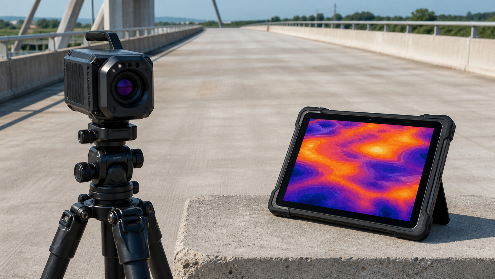
Infrared thermography can scan a concrete surface quickly and reveal thermal patterns that may indicate shallow delamination, overlay debonding, or other discontinuities. Its speed is attractive on bridge decks and large exposed slabs, but a colorful thermogram is not a diagnosis by itself. Solar exposure, wind, moisture, shadows, surface repairs, coatings, and defect depth can all change the pattern.
A defensible infrared survey treats every thermal anomaly as a location to investigate, not an automatic repair boundary. Owners get better decisions when the test plan defines the target defect, controls the survey window, records visible conditions, confirms representative indications, and connects the final map to engineering judgment.
What infrared thermography measures
An infrared camera measures thermal radiation emitted from a surface and converts it into an apparent surface-temperature image. It does not see through concrete like an X-ray. Instead, it detects differences in surface heating or cooling that can be caused by interruptions in heat flow below the surface.
In passive thermography, sunlight and ambient conditions provide the thermal stimulus. A shallow delamination may cause the concrete above it to warm and cool at a different rate than adjacent sound concrete. During favorable daytime warming, a suspect area may appear relatively warm; during cooling, the contrast can reverse. FHWA’s infrared thermography guidance explains this heat-flow principle and identifies delamination, overlay debonding, and void detection as common bridge applications.
Active thermography uses a controlled external heat source and observes the response during heating or cooling. It can reduce dependence on solar heating for smaller areas, but the heat input, distance, duration, access, and fire or electrical controls must be engineered for the site. It is not simply passive scanning with a heater added.
Where the method fits in a concrete assessment
Infrared thermography is most useful as a rapid screening and mapping tool on accessible surfaces with a reasonably uniform thermal exposure. ASTM D4788-03(2022) specifically addresses detecting delaminations in portland-cement concrete bridge decks, including exposed and overlaid decks. The standard’s application should not be expanded to walls, soffits, tunnels, façades, or unusual overlays without a project-specific procedure and suitable validation.
Good applications can include:
- screening large bridge-deck areas before targeted sounding or intrusive checks;
- mapping possible overlay debonding where the surface and environmental conditions are suitable;
- prioritizing detailed investigation zones on exposed slabs or concrete elements;
- tracking changes in a repeat survey when acquisition conditions can be made comparable; and
- combining thermal evidence with visual, sounding, corrosion, and material data.
The method should not be used to declare reinforcement corrosion, determine concrete strength, measure defect depth, or certify structural capacity. If the assessment question is corrosion activity rather than delamination geometry, tools such as half-cell potential mapping, concrete resistivity testing, and chloride sampling answer different parts of the problem.
Plan the survey before arriving on site
Define the target and decision
State what the survey is intended to find and what will happen with the results. “Scan the deck” is too vague. A useful scope might ask whether passive thermography can identify probable shallow delamination zones for confirmation and repair-quantity planning. Define the element, accessible face, expected construction, overlay type and thickness, known repairs, drainage paths, traffic controls, required positional accuracy, deliverables, and acceptance process.
Review drawings, inspection reports, repair records, leak locations, and previous survey maps. Existing patches, membranes, asphalt, sealers, paint, dirt, ponded water, and surface texture can change emissivity or heat flow. These features must be recorded rather than mistaken for subsurface distress.
Select a viable thermal window
Passive thermography depends on environmental excitation. The team should establish minimum pre-survey and survey-period requirements for solar loading, cloud cover, wind, precipitation, surface dryness, and temperature history based on the applicable procedure and site. A single air-temperature reading is inadequate. Log conditions over time and note every abrupt change.
Shadows from parapets, vehicles, equipment, utilities, adjacent buildings, or the bridge itself can create sharp thermal boundaries. Wind can reduce contrast. Moisture can alter both thermal conductivity and evaporative cooling. Recent rain, washing, or ponding may invalidate an otherwise convenient survey window. If conditions fall outside the plan, pause and document the rejected data rather than forcing an interpretation.
Choose coverage and location control
Set camera height, angle, speed, field of view, overlap, image interval, and route so the required surface resolution is achieved consistently. Pair thermal images with visible-light images. Use deck stations, grid marks, control points, or verified georeferencing so an anomaly can be found later by the confirmation and repair teams. A visually impressive mosaic has little construction value if its boundaries cannot be transferred to the concrete.
Field acquisition and QA/QC hold points
Document the equipment and setup
Record the infrared camera identification, calibration status, lens, thermal range, focus method, emissivity setting, reflected-temperature assumptions where applicable, image format, acquisition software, mounting arrangement, and distance from the surface. Allow equipment to stabilize as required by the manufacturer. A pre-survey functional check on a representative area helps expose focus, storage, battery, or synchronization problems before production scanning.
Capture thermal and visual context together
Thermal data should be traceable to visible surface conditions. Record patches, stains, wet areas, debris, markings, drains, joints, lane lines, shadows, and changes in material. Keep original radiometric files where the camera supports them; exported color images alone may discard temperature information and processing flexibility.
Operators should avoid auto-ranging each frame in a way that makes neighboring images look dramatically different despite similar temperatures. Processing settings, palettes, thresholds, and corrections must be documented and applied consistently. Preserve raw data separately from interpreted maps.
Use repeat passes and confirmation areas
Repeat selected passes to check whether indications persist and remain spatially consistent. Include areas believed to be sound and areas with known or readily confirmable defects. Where safe and accessible, compare representative hot, cold, ambiguous, and apparently sound zones using sounding, selective openings, cores, or another suitable nondestructive method.
The existing concrete delamination survey guide explains how chain drag and hammer sounding can support repair mapping. Impact-echo may help investigate selected internal reflectors; the impact-echo testing guide covers its planning and interpretation limits. Confirmation density should reflect the consequence of error, variability of the structure, and how the map will be used.
Interpret anomalies without overclaiming
Interpretation starts with the thermal history and visible context, not a universal temperature-difference threshold. Look for coherent shapes that persist across suitable images and are not explained by shadows, moisture, dirt, patches, surface texture, thickness changes, utilities, or boundary effects. Compare warming and cooling behavior when the scope permits.
FHWA research on nondestructive evaluation of concrete bridge decks with overlays found that technology performance changes with overlay type and defect location. Infrared thermography may reveal overlay debonding yet miss deeper, reinforcement-level delamination in some configurations. The correct output is therefore a map of interpreted anomaly classes and confidence—not a claim that every colored pixel is unsound concrete.
A useful classification might distinguish probable anomalies supported by repeat data and confirmation, possible anomalies requiring follow-up, surface or environmental artifacts, and areas not evaluated. State the effective survey area and exclusions explicitly. Quantities should include the mapping resolution and uncertainty appropriate to the intended estimate.
Key limitations owners should put in the report
- Environmental sensitivity: solar history, clouds, wind, ambient temperature, and moisture affect thermal contrast.
- Depth limitation: deeper defects produce weaker and broader surface signals, and exact depth is generally not obtained from passive imaging.
- Surface effects: coatings, overlays, patches, stains, debris, texture, and differing emissivity can mimic or hide anomalies.
- Geometry effects: edges, joints, drains, thickness changes, utilities, and shaded zones disrupt normal heat flow.
- No direct condition measurement: thermography does not directly measure bond strength, corrosion rate, compressive strength, or remaining structural capacity.
- Validation dependence: performance demonstrated on one area or construction may not transfer unchanged to another.
ASTM is developing broader guidance for passive thermography of exterior concrete. Its WK97864 work item highlights sensitivity to solar incidence, wind, moisture, defect depth, and surface condition, and notes that the prospective guide would not establish universal acceptance thresholds. Until any new document is approved, project teams should distinguish active standards from work in progress.
Turn the survey into a repair decision
Overlay the interpreted anomaly map with visual distress, sounding, corrosion indicators, drainage paths, traffic exposure, and structural details. Then have the responsible engineer decide where confirmation, removal, monitoring, or no action is appropriate. Repair boundaries should be finalized in the field after exposing sound concrete, not blindly cut from a thermal polygon.
For budgeting, separate confirmed defects from probable and possible anomalies. Include access, traffic management, verification testing, quantity variation, and disposal assumptions. When results will support a tender, provide the raw-data retention requirements, map coordinate system, confirmation basis, and rules for resolving discrepancies during construction.
Owner’s infrared thermography checklist
- Define the target defect, structure, accessible face, and decision the data must support.
- Specify the applicable standard or project-specific validated procedure.
- Review overlays, patches, moisture sources, shadows, and prior repairs.
- Set environmental go/no-go criteria and log conditions throughout acquisition.
- Require calibrated equipment, consistent geometry, raw radiometric data, and visible images.
- Provide reliable spatial control so findings can be relocated.
- Confirm representative anomalies and apparently sound areas with an independent method.
- Report confidence classes, exclusions, limitations, and mapping uncertainty.
- Have the engineer integrate the results with structural and durability evidence.
Frequently asked questions
Can infrared thermography confirm concrete delamination by itself?
Usually it should be treated as screening evidence. Representative anomalies and apparently sound areas should be checked with sounding, selective openings, cores, or another appropriate method before final repair quantities or structural decisions are made.
Does a hot spot always mean delamination?
No. Moisture, shadows, patches, coatings, dirt, geometry, thickness changes, and other surface or boundary conditions can create thermal anomalies. Interpretation must use visible context, environmental logs, repeatability, and confirmation.
Can thermography measure delamination depth?
Passive infrared thermography generally does not provide exact defect depth. Deeper defects are harder to detect, and their surface signatures can be weak or diffuse. Other methods or selective verification may be needed.
Is thermography useful on overlaid bridge decks?
It can be useful, and ASTM D4788 covers exposed and overlaid concrete bridge decks. Performance depends on overlay material, thickness, bond condition, moisture, defect depth, and survey conditions. The team should validate the method on representative construction.
Should infrared thermography replace sounding?
Not automatically. Thermography offers rapid, noncontact coverage; sounding provides a different physical indication and may be better suited to accessible confirmation. Combining methods can reduce the risk of relying on one ambiguous signal.
Need an evidence-based survey scope?
Structural Rehab can help owners define investigation objectives, select complementary test methods, establish QA/QC hold points, and translate condition data into practical repair decisions. Book a structural rehabilitation consultation to discuss your bridge, building, or concrete asset. Recommendations must be developed for the actual structure by qualified professionals; this guide is not a substitute for project-specific engineering.
Need a professional structural assessment?
Book a consultation with Structural Rehab to evaluate repair priorities, corrosion risks, and rehabilitation options before damage escalates.
Book Consultation