
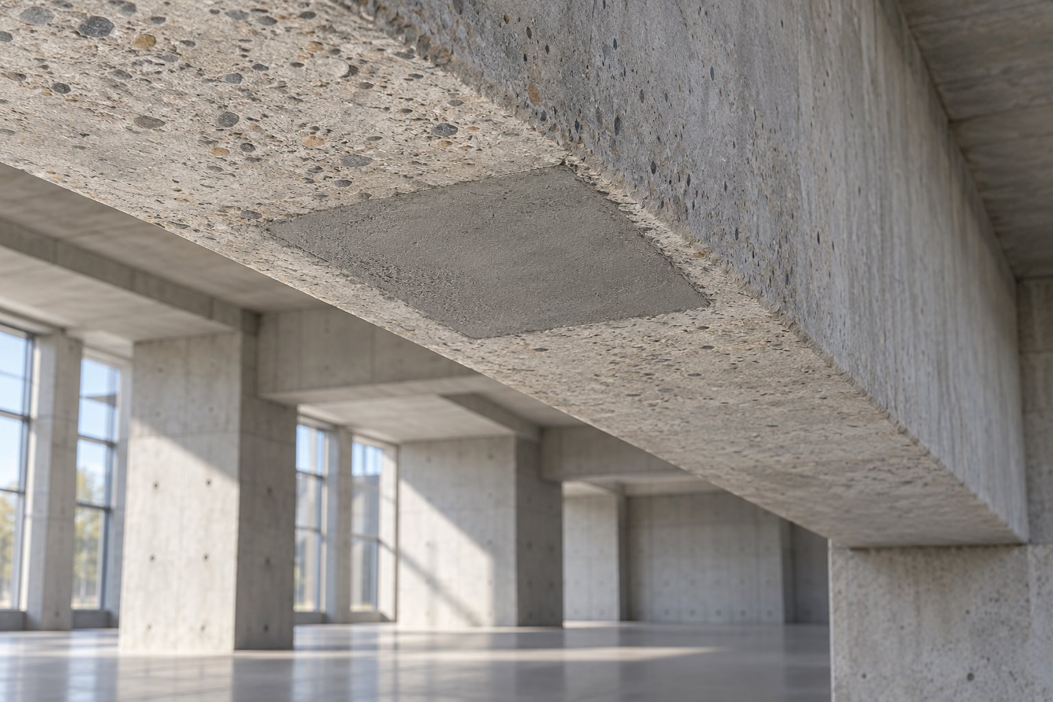
Overhead concrete patch repair needs a placement plan that works against gravity. A mortar can look neatly finished while concealing poor contact at the soffit or a weak interface between lifts. For localized hand-applied repairs, the useful questions are whether the cavity can be packed completely, whether each lift can support the next, and how those conditions will be recorded before they disappear.
A smooth soffit is not evidence of a sound repair interface. This guide focuses on planning and inspecting hand-applied cementitious patches to concrete beam and slab soffits. It does not provide a structural design or authorize removal from a loaded member. The featured illustration is conceptual and does not document an inspected project.
First decide whether hand application fits
ACI RAP-6 describes hand application as particularly useful for shallow repairs and identifies formed or sprayed methods as alternatives for larger or deeper work. Its guidance does not replace assessment of the existing structure. Select the method using the actual cavity, access and repair objective, rather than the size of the visible stain.
Ask the engineer to distinguish cover restoration from a repair intended to restore structural section or transfer force. A product described as a structural repair mortar does not, by that description alone, establish composite action or reinstate the member’s capacity. Unexpected reinforcement damage, widespread hollow areas, moving cracks or deterioration extending beyond the approved boundary require review before proceeding.
A useful method-selection meeting starts with photographs and a dimensioned sketch. Can the applicator see and reach the whole cavity? Is there a clear route for placing mortar around retained bars? Can the planned sequence be inspected? If the answers remain uncertain, compare an engineered form-and-pour repair or another suitable method before ordering material.
Make access and falling-material protection part of the scope
Overhead work creates exposure for people below as well as the repair crew. Plan access, debris containment, exclusion zones and the route used to remove waste. Keep occupants and unrelated trades outside the affected area. Temporary support, where required, needs an engineered arrangement and removal sequence; a working platform is not automatically structural shoring.
For US projects, OSHA 1926.501(c) addresses protection from falling objects through head protection and specified additional measures. Scaffold work also has its own applicable provisions. Outside that jurisdiction, apply local requirements. The project safety plan should address the particular access equipment, silica-producing preparation, wet cement contact and occupied spaces; this article is not a substitute for that plan.
Resolve the cavity before selecting a lift sequence
ACI’s field guide emphasizes sound concrete, prepared boundaries, clean reinforcement where exposed and an appropriate substrate condition. Confirm the specified preparation requirements against the approved material system. Do not convert a general illustration into a universal saw-cut depth or clearance detail: shallow reinforcement, tendons and embedded services change what can safely be removed.
Record maximum and minimum cavity depth, not just an average. Sketch deeper pockets and reinforcement obstructions. Give every patch a location identifier tied to a drawing or grid. A photograph should include context sufficient to find the patch again; an isolated close-up of gray concrete is difficult to use during a later investigation.
At this stage, the inspector’s release should identify the accepted boundary and any conditions still outstanding. For example, a repair may be ready geometrically but waiting for approval of a corroded bar. Mark that distinction explicitly so a material delivery does not accidentally become permission to cover unresolved work.
Use product-specific limits for each overhead lift
Do not assume that a vertical application limit also applies overhead. Obtain the current regional product data, proposed batch proportions and any written manufacturer clarification for the actual orientation. Verify minimum thickness, maximum lift thickness, total build, working time and the conditions for subsequent layers together.
As one product-specific example, the US SikaTop-123 Plus instructions list a layer range of 3 to 38 mm. They call for roughening between lifts, an initial-set interval of at least 30 minutes, SSD conditioning and a fresh mortar scrub-in. Those values are not generic overhead repair limits and should not be transferred to another product or regional formulation.
Translate the selected requirements into a short lift schedule: patch ID, planned lift number, permitted depth range, surface preparation, readiness condition and inspector. If the cavity varies significantly, mark the deeper portion on the sketch rather than allowing the whole patch to be built to that maximum. Obtain an approved detail where the planned final lift would be thinner than the product permits.
Demonstrate the difficult part first
For unfamiliar material or awkward geometry, propose a representative trial with the intended crew and access arrangement. The trial should address the hardest reach and the proposed lift sequence. Record what changed after the trial, such as batch size or access position. A demonstration on a convenient vertical board does not reproduce the working position under a beam.
Control placement without improvising the mix
The TxDOT intermediate-spall procedure requires measured components and mechanical mixing, prohibits retempering, and describes applying troweled repair material while its bonding layer remains in the required condition. It also addresses roughening and waiting between lifts. These are agency procedures; the contract and approved material instructions determine the requirements for a particular project.
Assign one person to maintain a simple batch record. Include product and lot, measured liquid, mixing start, placement start and finish, relevant temperatures, and patches receiving that batch. If several patches are being filled, their identifiers should travel with the batch record. This makes it possible to isolate an affected area if a proportioning error is discovered.
Keep substrate conditioning coordinated with placement. The site’s SSD substrate moisture guide explains why an earlier wetting record does not establish the condition at application. Use the approved bonding system consistently; do not add a second primer as an improvised remedy for poor workability.
Treat sagging as a stop point
If mortar slumps, peels or pulls away, stop placing onto the affected area and keep the exclusion zone in place. Record the patch, lift and batch before evidence is lost. Review thickness, proportions, substrate condition, timing and access with the responsible supervisor and technical team. Resume only with an accepted disposition; do not hide the defect by smoothing another layer over it.
Inspect each interface before it disappears
Use separate entries for substrate release and subsequent-lift release. The first confirms the prepared concrete and any reinforcement work. The later entry confirms the preceding lift’s condition, elapsed time, required texture and conditioning. Avoid a single end-of-shift signature that appears to approve interfaces nobody actually saw.
Consider this illustrative record: patch B7 received its first lift from batch M3; the next lift was delayed because access equipment had to move. The restart entry should explain the surface treatment and readiness checks performed after the delay. Merely copying the original placement time leaves the most important question unanswered: what condition was covered when work resumed?
Where the schedule changes, update the inspection plan before continuing. Name who can accept an interruption, who can seek manufacturer advice and who can approve a method change. This is especially useful when the engineer is not continuously on site. A clear decision route reduces pressure on the applicator to invent a solution while mixed material is aging.
Plan curing and acceptance before removing access
The cited Sika instructions require curing and warn that curing compounds can interfere with adhesion of later mortar lifts or coatings. Select a compatible method and arrange access to maintain it. Do not assume that the underside of a shaded slab is protected from drying simply because direct sunlight is absent.
Agree beforehand on when to inspect the completed patch, which tests apply, and who signs the release. TxDOT’s procedure includes visual inspection and sounding after curing. Additional project-specific evidence may be appropriate, but a photograph or compressive-strength result alone cannot demonstrate the condition of every repair interface. See the site’s pull-off testing guidance for planning and interpreting specified bond tests.
Keep the completion package compact and traceable: accepted repair dimensions, batch-to-patch map, interface releases, curing record, test locations and results, nonconformance dispositions, and final photographs. Distinguish cosmetic finish acceptance from technical acceptance. Record any remaining monitoring or coating work so the owner does not mistake a tidy surface for closure of every requirement.
Limitations and frequently asked questions
Can every soffit spall be repaired by hand?
No. Depth, access, reinforcement congestion, damage mechanism and structural function can favor a different method. Prestressed members and repairs affecting stability need specialist assessment and controlled removal details.
Is a non-sag label enough to approve the mortar?
No. Check the complete proposed system against the repair geometry, orientation and exposure, then document the approved placement procedure. Non-sag behavior does not establish the existing concrete’s suitability or the completed bond.
Can a crew use one standard waiting time between layers?
Only if that procedure is appropriate to the selected product and actual conditions. Record both the required timing and the required surface condition. Refer unexpected interruptions to the approved restart procedure.
When can occupants return beneath the repair?
After the responsible project team authorizes removal of the relevant restrictions using the repair, curing, access and safety requirements. Touch-hard mortar is not, by itself, a release criterion.
Prepare a reviewable overhead repair plan
Bring condition photographs, drawings, proposed materials and access constraints to a Structural Rehab consultation. Use the discussion to clarify the repair objective, lift sequence, inspection responsibilities and acceptance evidence before work begins.
Need a professional structural assessment?
Book a consultation with Structural Rehab to evaluate repair priorities, corrosion risks, and rehabilitation options before damage escalates.
Book Consultation