
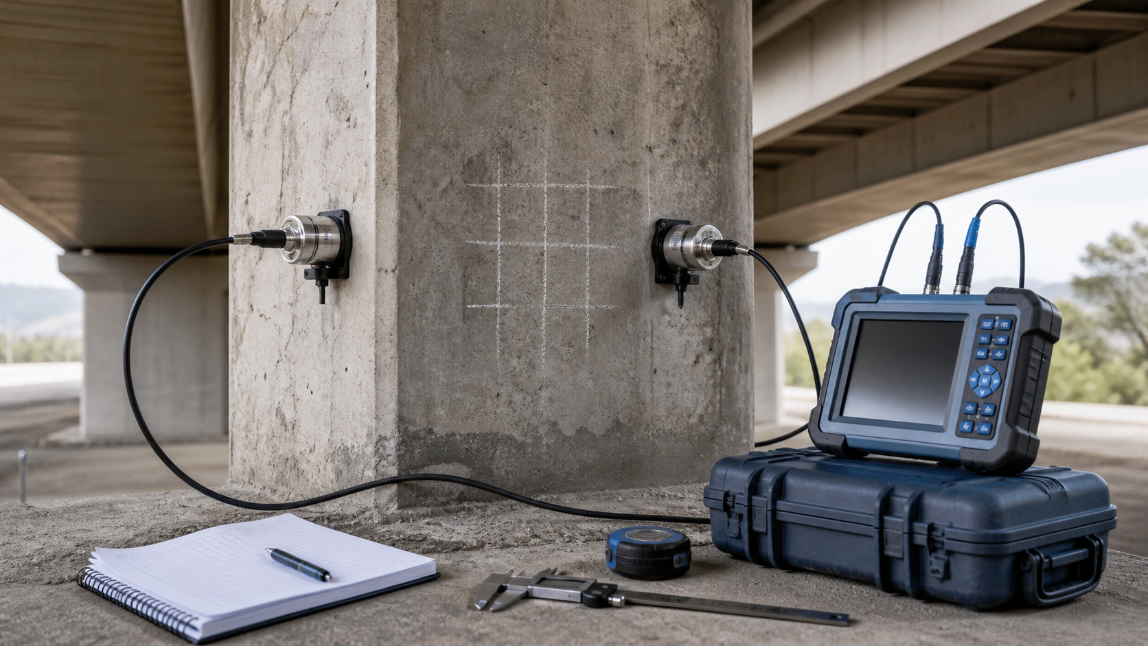
Ultrasonic pulse velocity testing can quickly compare the condition of concrete across a member, but the number on the instrument is not a direct compressive-strength result. Used correctly, UPV helps an engineer map relative uniformity, investigate suspected cracks or voids, compare repaired and unrepaired zones, and decide where targeted opening-up or cores will add the most value.
This guide explains how owners, engineers, and inspectors can plan ultrasonic pulse velocity concrete testing, control field variables, interpret results conservatively, and turn the survey into defensible repair decisions.
What ultrasonic pulse velocity actually measures
A UPV instrument sends a longitudinal stress-wave pulse from one transducer through concrete to another transducer. The instrument measures transit time. The apparent pulse velocity is the measured path length divided by that time. Elastic properties, density, moisture condition, cracking, voids, aggregate, reinforcement, path geometry, surface coupling, and instrument setup can all influence the result.
ASTM C597-22 identifies suitable uses including assessing uniformity and relative quality, indicating cracks and voids, evaluating crack-repair effectiveness, and tracking changes over time. It also makes an essential limitation clear: UPV results alone are not a measurement of concrete strength. A project-specific relationship is needed if strength estimation is intended.
Where UPV adds value before structural repair
Map relative changes rather than chase a universal threshold
A grid survey can reveal zones whose travel times differ consistently from comparable concrete. These anomalies can guide sounding, impact-echo, reinforcement locating, selective breakout, petrography, or concrete core testing. The most useful comparison is normally between like-for-like locations on the same structure under controlled conditions, not against a generic velocity classification.
Investigate cracks, voids, and honeycombing
Cracks or discontinuities can lengthen or interrupt the effective wave path, reducing apparent velocity or weakening the received signal. Orientation matters: a pulse path crossing a crack may respond differently from one running parallel to it. UPV can support investigation of suspected internal defects, but it does not automatically define defect shape, structural significance, or repair boundaries. Combine it with visual mapping, delamination surveying, and targeted verification.
For visible rock pockets or voiding, use the broader disposition process in the guide to honeycombed concrete repair. UPV is evidence within that process, not an automatic acceptance or rejection tool.
Compare crack repairs or repaired zones
Repeat measurements across a crack before and after injection may help demonstrate improved stress-wave transmission. That does not by itself prove complete resin fill, restored reinforcement bond, watertightness, or structural capacity. Define the acceptance question before testing, keep the measurement geometry repeatable, and pair UPV with material records, injection logs, observations, cores, or other verification where consequences justify it.
Choose the transmission arrangement deliberately
Direct transmission
With transducers on opposite faces, the pulse crosses the member on the shortest defined path. This generally provides the strongest signal and most reliable transit-time measurement, but both faces must be accessible and the path length must be measured accurately. The FHWA Underwater Bridge Inspection Reference Manual describes direct transmission as typically providing the most accurate results.
Semi-direct and indirect transmission
Semi-direct testing places transducers on adjacent faces. Indirect or surface transmission places both on the same face. These arrangements can be necessary when access is limited, but their wave paths and sensitivity differ. Do not mix configurations in one dataset without a documented procedure and suitable correlation. If only one face is available, consider whether impact-echo, ultrasonic surface waves, or another NDE method better answers the investigation question.
Build a field procedure that controls variability
- Define the decision. State whether the survey is mapping uniformity, screening suspected voids, assessing a crack, checking a repair, or supporting a calibrated strength estimate.
- Review drawings and scan first. Reinforcement can influence results, especially when the pulse travels along a bar. Use the project records and, where needed, rebar locating with a cover meter or GPR.
- Establish a grid and references. Mark stable coordinates and preserve photographs or sketches so anomalous and repeat locations can be found again.
- Record geometry. Measure the actual transducer spacing and identify direct, semi-direct, or indirect configuration. Small distance errors can materially affect calculated velocity on short paths.
- Prepare the contact points. Remove loose dirt or surface contamination without damaging the concrete. Rough or uneven surfaces may require local smoothing permitted by the test plan.
- Control coupling. Apply a consistent coupling medium and pressure. Confirm a stable arrival time or waveform rather than accepting a fluctuating reading.
- Record moisture and temperature. Saturation affects velocity; ASTM notes that saturated concrete may read higher than dry concrete. Avoid comparing wet and dry zones as though moisture were irrelevant.
- Repeat readings. Establish a project repeatability criterion and investigate unstable measurements immediately.
- Preserve raw data. Retain path length, transit time, calculated velocity, instrument details, calibration checks, grid location, surface condition, configuration, and observations.
QA/QC hold points for a reliable survey
Before testing
- Engineer-approved scope, grid, configurations, and decision criteria
- Instrument identification, calibration or reference-bar check, and suitable transducers
- Access and safety plan, including traffic, height, confined-space, water, or energized-service controls
- Known reinforcement, ducts, embedded items, repairs, coatings, and moisture differences mapped
- Reference areas selected from comparable concrete
During testing
- Stable coupling and repeat readings at suspect points
- No undocumented change in transducer frequency, configuration, operator method, or couplant
- Actual path length measured rather than inferred from nominal drawings
- Anomalies checked in more than one orientation where geometry allows
- Visible cracks, dampness, coatings, roughness, and nearby reinforcement logged
Engineering review before repair boundaries are fixed
A color contour plot is not an engineering disposition. The reviewer should examine repeatability, spatial pattern, geometry, moisture, reinforcement, and corroborating evidence. An isolated low reading with poor coupling is different from a repeatable cluster that aligns with sounding, cracking, or core evidence. The FHWA Federal Lands design guidance lists UPV among NDE options for internal flaws, cracking, honeycombing, and subsurface damage, while also placing it within a broader investigation toolbox.
Do not convert velocity directly into strength
Concrete with higher elastic stiffness often transmits waves faster, but strength is not determined by pulse velocity alone. Mix proportions, aggregate type, moisture, age, damage, and other variables can produce different strength at similar velocity. ACI guidance says a relationship must be established for the particular concrete, and notes that cores tested in accordance with ASTM C42 are the most accurate in-place approach among the referenced options.
If strength estimation is genuinely required, develop a statistically defensible project-specific correlation using representative cores or specimens and account for the factors affecting both tests. Do not borrow a chart from a different structure or material. Read the result alongside the engineer’s assessment, loads, deterioration mechanism, and the limitations of the sampling plan.
Turn the findings into a repair decision
Use UPV to refine—not replace—the investigation. Repeatable anomalous zones may justify targeted cores, localized breakout, impact-echo, petrography, chloride testing, or structural analysis. Normal-looking readings do not prove absence of corrosion or every form of deterioration. If corrosion risk is the question, combine the survey with methods such as half-cell potential mapping, resistivity, chloride profiles, and direct reinforcement observations.
Repair limits should follow the defect mechanism and required function. Where removal is needed, define temporary support, reinforcement protection, perimeter geometry, substrate preparation, material compatibility, placement, curing, and acceptance. A successful UPV survey narrows uncertainty; it does not transfer the engineer’s responsibility to an instrument.
Limitations owners should see in the report
- UPV indicates apparent wave velocity along the tested path, not a complete three-dimensional image.
- Moisture, temperature, reinforcement, aggregate, surface condition, coupling, path length, and geometry can affect readings.
- Crack orientation relative to the pulse path affects sensitivity.
- Indirect results should not be treated as interchangeable with direct results without validation.
- A velocity-strength relationship must be established for the specific concrete before estimating strength.
- Small or unfavorably oriented defects may not be detected.
- Interpretation requires qualified engineering judgment and, where necessary, corroborating tests.
FAQ
Can UPV find voids inside concrete?
It can indicate discontinuities or relatively poor zones through delayed travel time, reduced apparent velocity, or signal changes. It usually cannot define a void’s exact size and shape by itself. Confirm significant findings with complementary NDE or targeted opening-up.
What is a good ultrasonic pulse velocity for concrete?
There is no universal number that accepts every concrete structure. Project interpretation should compare controlled, like-for-like measurements and consider the concrete mixture, moisture, aggregate, geometry, reinforcement, age, and investigation objective.
Can UPV replace concrete cores?
No. UPV can reduce uncertainty and improve core targeting, but cores provide direct material for strength testing, petrography, and chemical evaluation. Use each method for the question it can answer reliably.
Can UPV verify epoxy crack injection?
Before-and-after measurements may support verification of improved wave transmission across a crack. They do not alone prove full resin penetration, watertightness, bond, or restored capacity. Define multiple acceptance records appropriate to the repair.
Should testing be repeated at the same locations?
Yes, when monitoring change or repair effectiveness. Permanently reference the coordinates and repeat the same geometry, equipment setup, surface preparation, and environmental records as closely as practical.
Plan the investigation before committing to repair
If an owner needs to distinguish isolated anomalies from a wider concrete problem, Structural Rehab can help define the investigation sequence, interpret evidence, and develop a repair scope with practical QA/QC hold points. Book a structural rehabilitation consultation to discuss the structure, access constraints, and decisions the testing must support.
Authoritative references
- ASTM C597-22, Standard Test Method for Ultrasonic Pulse Velocity Through Concrete
- ACI: How are properties of concrete in the structure measured?
- ACI: Is pulse velocity related to strength?
- FHWA Underwater Bridge Inspection Reference Manual
- FHWA Federal Lands Project Development and Design Manual, Chapter 10
Need a professional structural assessment?
Book a consultation with Structural Rehab to evaluate repair priorities, corrosion risks, and rehabilitation options before damage escalates.
Book Consultation