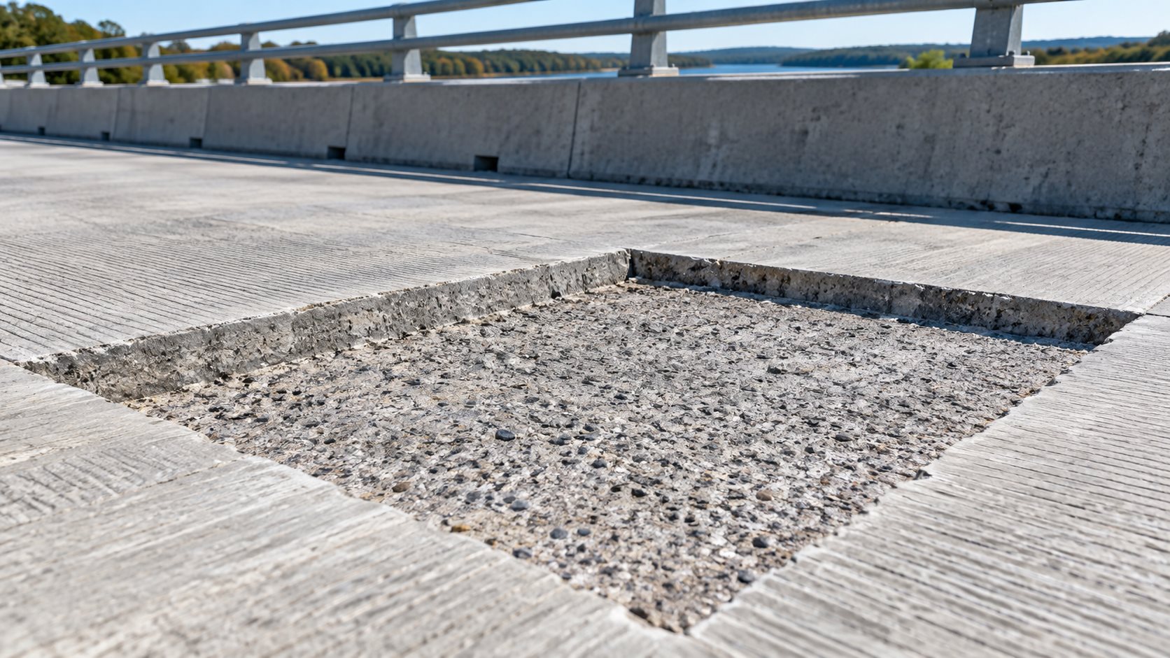
A bridge-deck patch is not automatically a partial-depth repair just because the visible spall is shallow. The repair depth has to follow the condition evidence: delamination depth, reinforcing-steel condition, chloride exposure, cracking, and the deck’s remaining structural behavior. Choosing a shallow patch when deterioration continues below it can leave a weak interface and allow damage to return. Choosing full-depth replacement where only the cover zone is affected can add cost, traffic disruption, and risk to sound reinforcement.
This guide helps owners, designers, and inspectors make the partial-depth versus full-depth decision for localized concrete bridge-deck repair. It is not a substitute for project-specific analysis, agency specifications, traffic-control planning, or a licensed engineer’s repair design.
Start with the repair question, not the patch material
The first question is what has failed. A deck can show spalling from reinforcement corrosion, delamination caused by chlorides, freeze-thaw damage, impact, leaking joints, poor original consolidation, or a previous repair that lost bond. A compatible mortar cannot correct an active water path, widespread corrosion, or a deck that is structurally deficient.
Review drawings, maintenance history, previous patch maps, drainage details, and traffic exposure. Then map visible cracking, spalls, and delaminations. Sounding is useful for locating likely shallow delamination, but it is a screening tool rather than proof of depth. Use representative cores, cover measurements, selective exposure, or other qualified investigation methods where the repair classification is uncertain. The site’s guides to concrete delamination surveys, concrete core testing, and rebar locating explain those adjacent evidence streams.
FHWA’s pavement-repair guidance is a useful decision reference: partial-depth work is generally limited to shallow distress in the upper portion of a slab, while deterioration that reaches deeper, exposes dowels, or cannot be completely removed should trigger full-depth repair. A bridge deck is not identical to a pavement slab, so the agency’s bridge specifications and the engineer’s design govern. The lesson still holds: repair geometry must remove the defective concrete without creating a new structural problem.
When partial-depth deck repair can be appropriate
A partial-depth repair is commonly considered when distress is local and confined to the near-surface cover zone, the remaining concrete below the removal line is sound, and the repair can be detailed without compromising the reinforcement or a working joint. Typical candidates include localized delamination, spalls, scaling, or shallow deterioration around a leaking detail after the leak path is addressed.
The engineer should define the maximum removal depth, repair boundaries, edge geometry, surface preparation, material system, bond condition, curing, texture, and opening criteria. Do not set depth only from the saw cut. The crew should remove concrete until sound substrate is reached within the approved limits; if that effort exposes reinforcing steel, finds deeper weakness, or encounters conditions outside the design assumptions, the work must stop for disposition.
A partial-depth patch has to be treated as a bonded repair system. Its success depends on a sound, rough substrate; clean reinforcement where required; a material compatible with the deck and exposure; consolidation; curing; and protection from early traffic. The surface-preparation and curing requirements must be explicit in the project QA/QC plan.
Conditions that point toward full-depth repair
Full-depth repair is not merely a deeper patch. It is a structural removal-and-replacement operation with consequences for load transfer, reinforcement continuity, deck support, joints, and traffic staging. It becomes a serious candidate when deterioration extends through the deck thickness, reinforcement is significantly affected, a crack or joint condition needs to be reinstated, the concrete below a proposed shallow repair is unsound, or the engineer finds that a partial-depth interface would remain in a damaged zone.
Full-depth work needs a designed sequence. The documents should identify cut limits, temporary support or traffic restrictions where required, reinforcement treatment and splice details, any connection to adjacent concrete, forms, material placement, consolidation, curing, joint restoration, and acceptance criteria. An unplanned deep breakout can damage sound concrete or bars and change the load path. Field personnel should never enlarge a patch into a full-depth opening without the project’s approved response procedure.
Where damage is widespread rather than isolated, repeated patches may be the wrong asset-level answer. A deck-specific rehabilitation plan may need to compare patching with an overlay, cathodic protection, membrane replacement, or deck replacement. Structural Rehab’s UHPC bridge deck overlay guide describes one option that may enter that engineering comparison; it should not be selected without condition and life-cycle evaluation.
A field decision workflow that prevents scope drift
1. Establish the map and repair classes
Before removal, identify each repair area by station or grid and assign it a preliminary class: investigate, partial depth, full depth, or hold for engineering review. Record the evidence used. This prevents a crew from treating every marked spall as the same condition and creates a traceable basis for quantity changes.
2. Set conversion triggers in writing
The repair plan should state what converts a partial-depth area to full depth or requires another investigation. Useful triggers include unsound concrete below the approved limit, exposed or damaged reinforcement, unexpected voids, a crack that continues through the section, active leakage, or a boundary that reaches a joint or adjacent repair. The trigger is not a field permission to improvise; it is a stop-work and notification rule.
3. Control the removal boundary
Survey repair limits, saw-cut or otherwise form the specified boundary, and use equipment appropriate for the intended depth. Protect embedded reinforcement and utilities. Inspect the bottom and edges after removal for soundness and contamination. Record the actual depth and any deviation before substrate preparation begins. The goal is a deliberately accepted repair cavity, not a cavity that simply looks clean from the top.
4. Verify substrate, steel, and moisture condition
Confirm that weak concrete is removed, loose debris and dust are gone, and the specified surface condition is achieved. Where steel is exposed, the engineer’s detail should state cleaning, section-loss assessment, supplemental reinforcement, corrosion-control measures, and cover restoration. Moisture condition must match the selected bonding or repair system; see SSD substrate moisture before concrete repair for why a generic “wet” or “dry” instruction is inadequate.
5. Place, cure, and accept the repair
Check material identity, batch, water addition, mixing time, working time, ambient and substrate temperature, placement method, consolidation, finish, texture, cure, and opening-to-traffic requirements. The finished patch must meet the specified profile and drainage intent; a smooth-looking repair that ponds water can accelerate the next deterioration cycle. Retain photographs, daily records, test results, and accepted deviations.
The repair depth is a condition decision documented at the cavity, not a cosmetic decision made from the spall perimeter. That principle gives the owner a defensible record when repair quantities or traffic staging change.
Common mistakes to avoid
- Leaving a delaminated layer below the patch: use defined investigation and acceptance methods; do not stop removal at the initial planned depth when the substrate remains unsound.
- Cutting or undermining reinforcement: locate steel, establish safe removal limits, and obtain engineering direction for every unexpected finding.
- Patching before fixing water entry: evaluate joints, drains, membranes, and leakage paths; a patch is not a drainage repair.
- Using one material rule for every cavity: select materials for geometry, placement method, exposure, modulus, shrinkage, bond, cure, and required reopening time.
- Turning a local repair into a deck strategy by default: evaluate whether damage distribution calls for an overlay, protection system, or replacement instead.
Limitations and owner questions
Depth rules in published guidance are often tied to a particular pavement, bridge agency, material, or construction method. They are decision aids, not universal bridge-deck details. Existing deck thickness, reinforcing layout, post-tensioning, composite action, traffic loading, agency standards, and environmental exposure can all change the correct repair detail. Where a bridge carries live traffic or has uncertain capacity, a qualified engineer must determine the safe sequence and restrictions.
Before authorizing work, an owner should ask: What evidence supports the repair class? What will cause conversion to full depth? Who approves a changed boundary? How will reinforcement findings be evaluated? How are water entry and future corrosion being addressed? What records demonstrate that each repair was accepted before placement?
Frequently asked questions
Can a contractor decide to make every bridge-deck patch partial depth?
No. Partial-depth repair is appropriate only where the assessment and approved design show that deterioration is shallow and the remaining substrate is sound. Deeper or structurally relevant damage needs engineering review and may require full-depth repair or another rehabilitation strategy.
Does exposed reinforcing steel automatically require full-depth repair?
Not automatically, but it is a conversion trigger that needs the engineer’s disposition. The assessment must address concrete condition, steel section loss, cover, development, corrosion mechanism, and the approved repair detail.
How can an owner control unexpected quantities?
Require mapped repair IDs, pre-established conversion triggers, cavity acceptance records, photographs, and documented approval for changed work. Those controls are more reliable than trying to predict every repair depth from a surface survey alone.
Plan bridge-deck repairs around evidence and hold points
Partial-depth and full-depth repairs each have a place in concrete bridge-deck rehabilitation. The durable choice is the one that removes the actual damage, preserves or reinstates structural behavior, controls water and corrosion risks, and is documented through placement and cure. Structural Rehab can help owners frame an assessment and QA/QC scope before repairs begin. For a project-specific discussion, visit the consultation booking page.
Sources
- Federal Highway Administration: Partial-Depth Repairs—Construction
- Federal Highway Administration: Partial-Depth Repairs—Design Considerations
- Federal Highway Administration: Full-Depth Repairs—Construction Procedure
- Federal Highway Administration: Full-Depth Repairs—Performance
Need a professional structural assessment?
Book a consultation with Structural Rehab to evaluate repair priorities, corrosion risks, and rehabilitation options before damage escalates.
Book Consultation