
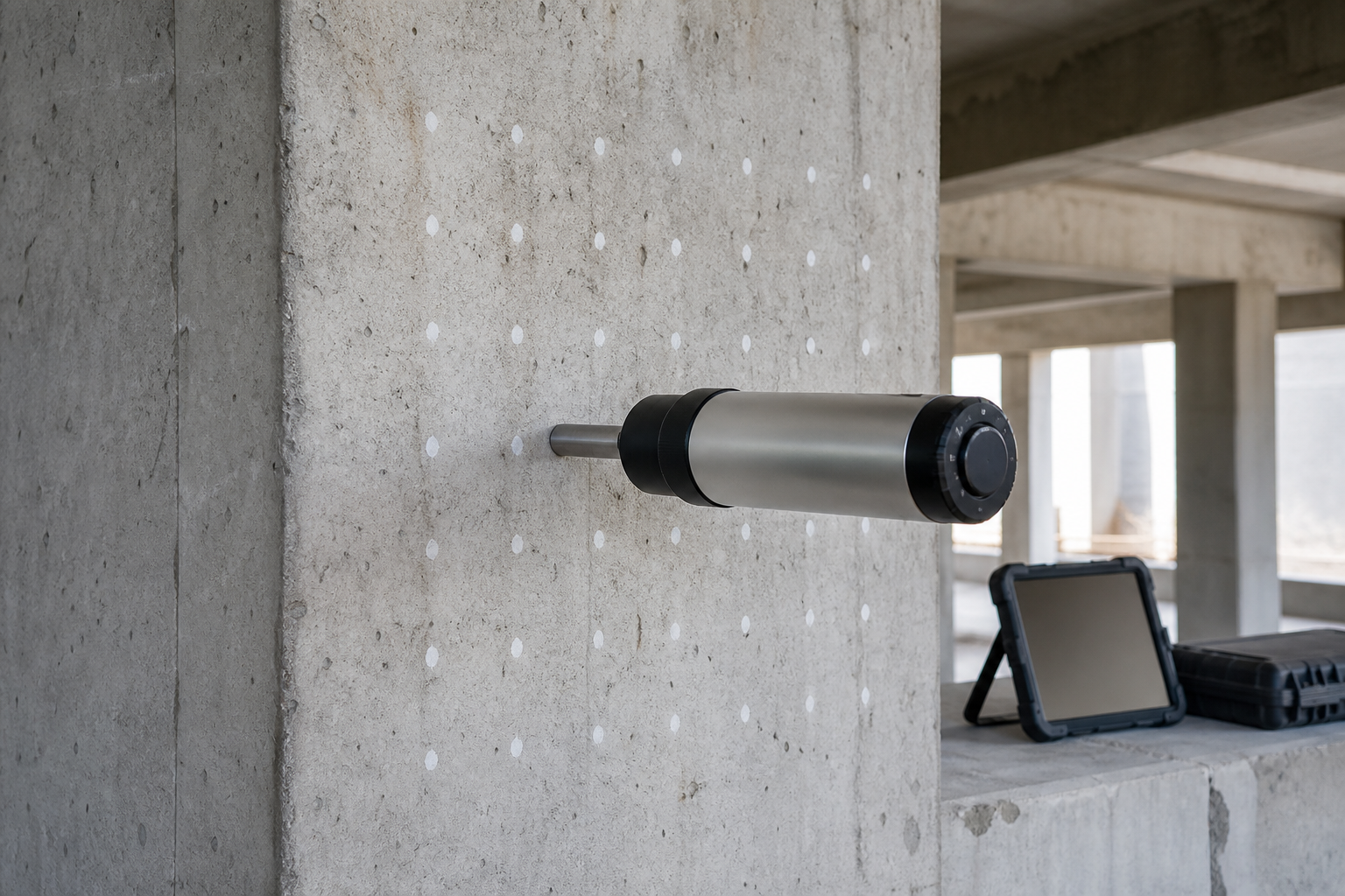
Rebound-hammer testing is a fast way to compare near-surface hardness across existing concrete. Used well, it can map relative uniformity, identify areas that deserve closer investigation, and help select representative core locations. Used carelessly, a convenient instrument reading can become a misleading strength number.
This guide explains how owners, engineers, and inspectors should plan rebound hammer concrete testing, control field variability, interpret results, and decide when cores or other methods are needed. The test is one line of evidence; it does not replace structural evaluation, laboratory testing, or project-specific engineering judgment.
What a rebound hammer actually measures
A spring-driven mass impacts a plunger held against the concrete. The instrument reports a rebound number related primarily to hardness near the tested surface. ASTM C805/C805M-25 covers the test and identifies appropriate uses: assessing in-place uniformity, delineating regions of poor-quality or deteriorated concrete, and estimating strength development when a valid project-specific relationship has been established.
The distinction matters. A rebound number is not compressive strength. Concrete moisture, surface finish, carbonation, aggregate, orientation, member condition, and the individual hammer can influence the reading. ASTM says the method is not intended as the basis for accepting or rejecting concrete because estimated strength carries inherent uncertainty.
The American Concrete Institute likewise explains that ACI 301 permits rebound hammer testing to evaluate uniformity or select areas to be cored. Strength estimation requires properly calibrated equipment and an acceptable relationship between the in-place test result and concrete compressive strength.
Good uses and poor uses
A rebound survey is a good fit when the engineering question is comparative. Examples include:
- mapping whether a column, wall, slab, or group of members has broadly uniform near-surface response;
- screening for zones that differ materially from comparable reference concrete;
- selecting core locations that represent low, typical, and high response zones;
- checking relative strength development when a mixture-specific relationship was established in advance; and
- supporting a wider investigation after fire, weathering, placement defects, or suspected deterioration.
Poor uses include reading a generic conversion chart as if it were a laboratory compression test, comparing unrelated mixtures, accepting a structure from rebound numbers alone, or reporting a few convenient readings as representative of an entire building. A successful rebound-hammer survey organizes uncertainty; it does not erase it.
Plan the survey around a decision
Define the population
Identify which members may reasonably be compared. Separate concrete placed at different times, supplied from different mixtures, exposed to different moisture conditions, or finished differently. Record member type, orientation, age, exposure, visible distress, coatings, repairs, and suspected carbonation. Combining unlike populations can create a neat-looking dataset with little engineering meaning.
Review existing evidence
Gather drawings, batch records, cylinder results, previous cores, repair histories, exposure records, and distress maps. If reinforcement or prestressing location is uncertain, use rebar locating before concrete repair to support safe core planning. If the concern is internal uniformity rather than surface hardness, coordinate the survey with ultrasonic pulse velocity testing or another suitable method.
Lay out representative test areas
Use a documented grid or test-area plan. Include apparently sound reference zones and suspect zones, while avoiding edges, corners, obvious voids, exposed aggregate pockets, severely scaled areas, and locations directly over reinforcement where the applicable procedure requires clearance. Mark every test area so results can be traced to photographs and drawings.
The survey density should match the variability and consequence of the decision. A few readings may support reconnaissance; they cannot define repair boundaries for a large or highly variable structure. Establish in advance how anomalous areas will be retested and what evidence will trigger coring.
Field QA/QC controls
1. Verify the instrument
Identify the hammer by serial number and impact energy. Check its condition and verify performance with the reference anvil at the required intervals. ASTM notes that hammers of the same nominal design can produce different rebound numbers, so comparisons should use the same instrument where practicable. If multiple hammers are unavoidable, quantify their difference on representative concrete and document it.
2. Prepare and document the surface
Test on a firm, smooth surface appropriate to the standard procedure. Remove loose material and document any grinding used to create a suitable area. Do not quietly test through coatings or over obviously weak laitance. Record whether the surface is dry or wet, formed or finished, carbonated, weathered, repaired, or fire-affected; these conditions can change the response.
3. Control orientation and support
Hold the plunger perpendicular to the test surface and record the hammer orientation. Thin or poorly supported elements may move or vibrate under impact and produce unreliable readings. Confirm that the member has adequate mass and restraint for the selected instrument. Do not treat orientation corrections as a substitute for consistent field technique.
4. Take a complete test set
Follow the current ASTM requirements for spacing, number of impacts, surface condition, and treatment of readings. Do not cherry-pick attractive values or average readings collected from visibly different substrates. Preserve individual readings, excluded results, the reason for exclusion, the calculated test-area result, and technician observations.
5. Repeat questionable areas
Review results while still on site. Repeat erratic areas after checking surface preparation, instrument condition, orientation, and member support. If the second set remains inconsistent, report the limitation and investigate with another method instead of forcing a strength interpretation.
Why generic strength charts are unsafe
Manufacturer charts may illustrate instrument behavior, but they do not establish the strength of an unknown structure. ASTM requires a relationship for the specific mixture and apparatus when rebound number is used to estimate strength. For an existing structure, that relationship is developed by correlating rebound measurements with cores from corresponding locations.
ACI’s guidance on in-place strength testing lists several available methods and notes that they generally require a strength relationship; it identifies cores tested in accordance with ASTM C42 as the most accurate approach. The ACI 228.1R-19 preview also emphasizes that a valid relationship between in-place results and compressive strength is required.
A correlation program should cover the strength range and concrete populations relevant to the decision. Pair test areas with carefully selected core locations, document moisture and surface condition, avoid reinforcement, and use qualified laboratory testing. Our guide to concrete core testing before repair explains how to connect core sampling to strength, petrography, chloride evidence, and the engineering question.
Interpret patterns before numbers
Start with spatial patterns. Does one placement, elevation, exposure face, or distress zone show consistently lower response than comparable concrete? Do abrupt changes align with a construction joint, repair boundary, wet area, fire exposure, or surface treatment? A contour map can help, but it must show test locations, invalid areas, and the population used for comparison.
Low rebound does not identify a cause. It may reflect weak concrete, a wet surface, poor finishing, scaling, microcracking, or another surface condition. High rebound may reflect carbonation or a hard dry surface rather than strong concrete through the member depth. Investigate causes using visual examination, sounding, cores, petrography, chemistry, or stress-wave methods as appropriate.
For suspected internal reflectors, impact-echo concrete testing addresses a different question. For mapped corrosion risk, combine condition observations with methods such as half-cell potential testing rather than inferring corrosion from rebound values.
Limitations owners should see in the report
- Surface sensitivity: the measurement primarily reflects near-surface hardness, not the full member depth.
- Moisture and carbonation: both can shift readings and distort comparisons.
- Mixture dependence: aggregate and mixture differences prevent a universal strength conversion.
- Geometry and support: thin, flexible, curved, or poorly supported elements may not respond reliably.
- Local influence: reinforcement, edges, roughness, repairs, and defects can affect individual impacts.
- No standalone acceptance: rebound results alone are not a defensible acceptance or rejection basis.
Minimum deliverables checklist
- survey objective, member populations, and decision criteria;
- test-area plan tied to drawings and photographs;
- hammer model, serial number, impact energy, and anvil verification records;
- surface preparation, moisture, finish, orientation, and support conditions;
- all individual readings, exclusions, test-area results, and repeat tests;
- maps comparing like concrete populations;
- core-correlation data when strength is estimated;
- limitations, anomalous zones, and unresolved uncertainty; and
- recommendations for coring, analysis, monitoring, repair, or no action.
Frequently asked questions
Can a rebound hammer determine concrete compressive strength?
Only as an estimate supported by a valid relationship for the relevant concrete and instrument. For existing structures, correlate readings with cores from corresponding locations. Do not use a generic chart as project evidence.
Can rebound testing replace cores?
It can improve core selection and reduce indiscriminate sampling, but cores remain necessary when direct strength, depth condition, petrography, chemistry, or visual confirmation is required.
Can wet and dry areas be compared?
Not casually. Surface moisture affects rebound response. Record moisture condition and compare areas under equivalent conditions or account for the limitation in the test plan and interpretation.
Is a high rebound number always good?
No. A carbonated or unusually hard surface may produce a high number that is not representative of concrete at depth. Interpret the reading with exposure, surface condition, and corroborating evidence.
Who should interpret the survey?
Qualified testing personnel should collect traceable data, while the engineer responsible for the structure should integrate results with geometry, loads, deterioration mechanisms, cores, and other investigation findings.
Use the test to guide the next decision
Structural Rehab helps owners develop assessment programs, repair scopes, and QA/QC hold points grounded in site evidence. For project-specific support, visit our consultation page. The best rebound-hammer program is not the one with the most readings; it is the one that clearly changes or confirms an engineering decision.
Engineering note: This article provides general education, not a project-specific test specification, structural assessment, or safety determination. Qualified professionals should evaluate existing structures using applicable codes, standards, and site information.
Need a professional structural assessment?
Book a consultation with Structural Rehab to evaluate repair priorities, corrosion risks, and rehabilitation options before damage escalates.
Book Consultation