
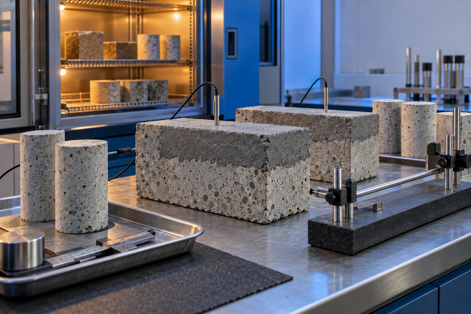
Thermal compatibility of concrete repair materials matters whenever a repaired member experiences daily, seasonal, operational, or fire-related temperature change. Existing concrete and a bonded repair expand when heated and contract when cooled. If they move by substantially different amounts, restraint at the interface can create cracking, debonding, edge lifting, or distress in the weaker material.
The coefficient of thermal expansion, commonly shortened to CTE, describes length change per degree of temperature change. It is useful evidence, but it is not a stand-alone product ranking. Repair geometry, temperature range, elastic modulus, creep, shrinkage, bond, substrate strength, moisture, thickness, restraint, and rate of temperature change all influence the stress that actually develops.
Why thermal compatibility belongs in repair design
A bonded repair is a composite system. The new material cannot freely expand or contract where it is attached to existing concrete. A small CTE difference may be tolerable in a compact sheltered patch, yet become important across a large overlay, long facade band, bridge deck, roof slab, industrial floor, chimney, tank, or member exposed to solar heating and rapid cooling.
The Bureau of Reclamation’s peer-reviewed compatibility report explains that differential thermal movement can create interface stresses and may cause bond failure or fracture within the weaker material. It also notes that many cement-based repairs are reasonably compatible with existing concrete under ordinary conditions, while massive repairs and some very fast-setting materials can experience significant heat rise followed by contraction. The implication is not that one material family is always safe or unsafe; it is that the proposed system must be evaluated for its real exposure and restraint.
Thermal behavior should be considered alongside the broader compatibility factors in concrete repair material selection. A high compressive strength or fast return-to-service time does not compensate for incompatible deformation.
Define the temperature exposure first
Before requesting laboratory numbers, define what the repair will experience. Record historical ambient temperatures, solar orientation, surface color, wind, shading, rainfall or washdown, freeze-thaw exposure, process heat, steam, refrigeration, fire history, and shutdown cycles. Surface temperatures can differ materially from nearby air temperatures, particularly on dark horizontal surfaces or thin exposed members.
Identify whether temperature changes are uniform through the repair or create a gradient. Rapid heating of an overlay surface while the substrate remains cooler can cause curling and interface stress. A thick placement may heat internally during hydration and then contract as it cools. Equipment foundations, furnaces, cold rooms, tanks, bridge decks, and external walls each create different thermal histories.
The design basis should state the service temperature range, credible rate of change, number of cycles, moisture condition, and whether exceptional events must be considered. Do not simply copy a generic regional air-temperature range into the specification.
Understand what the CTE number represents
CTE is calculated from measured length change divided by original length and temperature change. Results depend on test method, specimen condition, temperature interval, moisture state, age, aggregate type, and material composition. Values from different methods or conditioning regimes may not be directly comparable.
For conventional concrete, aggregate mineralogy strongly affects CTE. A repair mortar without coarse aggregate may behave differently from the existing concrete; an extended repair material may change when the approved aggregate is added. Polymer-modified and resin-based systems can have temperature-dependent properties that are not captured by a single room-temperature value.
Ask the supplier or laboratory for the test method, specimen age, cure, moisture conditioning, temperature range, number of specimens, individual results, average, variability, and units. A CTE value without its method and conditioning history is not a compatibility decision.
Choose tests that answer the project question
Coefficient testing
Coefficient testing can compare the proposed repair with cores or representative concrete made using similar aggregate. FHWA describes concrete CTE measurement using a conditioned cylinder in a variable-temperature water bath, reflecting the approach that informed the AASHTO concrete test method. The project laboratory should use the adopted current method and report specimen saturation and conditioning because moisture can affect the result.
Composite thermal cycling
A component-level test can be more informative when the primary concern is whether a bonded system survives cycling. ASTM C884/C884M-23 evaluates thermal compatibility between concrete and an epoxy-resin overlay by repeatedly cycling the bonded combination over a defined temperature range and observing debonding. ASTM explicitly limits the method to epoxy-mortar overlays for concrete pavement and says it is not intended to duplicate field temperature fluctuations.
That limitation matters. C884 should not be presented as a universal test for every cementitious patch, grout, jacket, membrane, or structural overlay. A project-specific mockup or laboratory program may instead combine relevant conditioning with bond, cracking, dimensional, or visual evaluation. The engineer should define the acceptance logic before results are known.
Heat-rise monitoring
For thick repairs, rapid-setting systems, or restrained placements, monitor temperature development during a representative trial. Embedded sensors can record peak temperature, gradients, and cooling rate. Pair the temperature history with mixture, batch size, initial temperature, geometry, insulation, ambient conditions, curing, and time. The same material can develop a different thermal profile in a small laboratory specimen and a large field placement.
Use the project’s repair mockup or trial panel to confirm constructibility and monitoring arrangements before production.
Evaluate the repair and substrate as a system
Comparing two CTE averages is only the first screen. Estimate differential strain over the design temperature change, then assess how repair geometry and restraint convert that movement into stress. A thin overlay, deep patch, jacket, narrow crack repair, bearing plinth, and large replacement block do not behave alike.
Review these interacting properties:
- Elastic modulus: a stiffer repair can develop higher stress for the same restrained strain.
- Creep and stress relaxation: time-dependent deformation may relieve some sustained stress but should not be assumed without evidence.
- Drying and autogenous shrinkage: thermal contraction can add to shrinkage rather than act alone.
- Bond and substrate tensile capacity: a strong adhesive does not prevent fracture in weak near-surface concrete.
- Repair thickness and area: larger or thicker placements can create gradients and higher hydration temperature.
- Joints and edges: terminations, corners, penetrations, and abrupt thickness changes concentrate stress.
- Moisture and freeze-thaw: thermal cycles combined with saturation can introduce a separate durability mechanism.
The preceding day’s concrete repair shrinkage testing guide explains why free-shrinkage and restrained-ring data answer different questions. Thermal and shrinkage compatibility should be assessed together when environmental deformation governs.
Design and specification controls
A performance-oriented specification should identify the exposure and required evidence without inventing a universal maximum CTE difference. Require traceable data for the proposed material and extension aggregate, use the correct test method, and define whether the objective is a property comparison, a bonded-cycle demonstration, temperature-rise control, or a combination.
For large or sensitive repairs, consider placing sequence, panel dimensions, joints, bond breakers where designed, edge detailing, insulation, cooling, lift thickness, batch temperature, cure duration, and time of placement. Thermal-control measures must be coordinated with moisture retention and early-age protection; aggressive cooling or premature exposure can damage a young repair.
Do not change approved aggregate, water content, accelerator, polymer component, or batch proportions without engineering review. These changes can affect thermal behavior as well as strength, shrinkage, working time, and durability. Keep the qualified mixture and field controls traceable throughout production.
Production monitoring and acceptance
Before placement, verify the substrate and ambient temperatures, approved material, lot, component temperatures, batch proportions, sensor locations, placement sequence, insulation or protection, and acceptance responsibilities. These items belong in the project’s pre-placement inspection hold point.
During placement, record batch and location traceability, material temperature, start and finish times, weather, repair depth, sensor readings, protection changes, and interruptions. Continue temperature monitoring long enough to capture the specified peak and cooling period. Evaluate sudden excursions against the written plan; do not remove protection or load the repair based only on elapsed time.
After curing, inspect cracks, edges, joints, surface condition, sounding response, bond evidence, and sensor records. If direct-tension tests are specified, interpret both the value and failure location using the principles in pull-off testing for repair bond. A passing specimen away from a distressed edge does not automatically accept the entire area.
Common mistakes
- Selecting the highest-strength material without comparing deformation properties.
- Comparing CTE values from different methods, units, ages, or moisture conditions.
- Using an epoxy-overlay thermal-cycling method as a universal test for all repair systems.
- Ignoring solar heating, operational cycles, or hydration heat because ambient air seems moderate.
- Testing only the repair material and not characterizing the existing substrate.
- Changing aggregate extension or admixture dosage after qualification.
- Assuming good initial bond guarantees long-term compatibility.
- Setting a numerical acceptance limit without structural analysis or exposure context.
Limitations
This guide does not establish a universal CTE value, allowable mismatch, cycling range, specimen condition, temperature limit, sensor spacing, or acceptance criterion. Those decisions depend on the structure, material system, governing documents, exposure, geometry, restraint, risk, and adopted test methods. Laboratory cycling accelerates selected mechanisms and may not reproduce field gradients, moisture, aging, loading, or workmanship.
Frequently asked questions
Should a repair material have exactly the same CTE as the existing concrete?
Not necessarily. Closer values can reduce differential movement, but performance also depends on temperature range, modulus, creep, shrinkage, bond, geometry, and restraint. The engineer should assess the complete system.
Is ASTM C884 suitable for cementitious patch repairs?
ASTM C884/C884M-23 is scoped to epoxy-resin overlays on concrete pavement. It should not be described as a universal cementitious-patch test. Select or design a method appropriate to the actual repair system and question.
Why does specimen moisture condition matter?
Concrete thermal response can vary with moisture condition. Conditioning also affects whether results from repair and substrate specimens are comparable. Reports should state the procedure rather than giving an isolated number.
Can thermal incompatibility cause failure even when pull-off strength is high?
Yes. Restraint can shift failure into the weaker substrate, the repair, or an edge zone. Initial pull-off strength does not reproduce every future temperature cycle or gradient.
When is temperature monitoring most useful?
It is especially useful for thick, rapid-setting, insulated, highly restrained, or temperature-sensitive placements and where opening, loading, or protection decisions depend on the actual thermal history.
Sources and further guidance
- Bureau of Reclamation: Compatibility Issues in Design and Implementation of Concrete Repairs and Overlays
- ACI PRC-546.3-23: Materials Selection for Concrete Repair
- ASTM C884/C884M-23: Thermal Compatibility Between Concrete and an Epoxy-Resin Overlay
- FHWA: Coefficient of Thermal Expansion Testing for Concrete
- ACI technical guidance on dimensional and mechanical compatibility of surface repairs
Need help comparing repair-material compatibility data, planning a thermal trial, or defining inspection hold points? Book a Structural Rehab consultation or use the free structural health ebook to organize questions before repair work begins.
Need a professional structural assessment?
Book a consultation with Structural Rehab to evaluate repair priorities, corrosion risks, and rehabilitation options before damage escalates.
Book Consultation